Sunday, November 22, 2009

YouTube supports 3D stereoscopic video

Google's video service YouTube now supports stereoscopic video. This is great news. I predict that soon it will be possible to stream stereoscopic YouTube videos to stereoscopic monitors.

The only technical information so far is one very long help thread. The Google engineer behind 3d YouTube, "YouTube Pete", participates in that thread.

I would like to take a moment to thank YouTube Pete for his beautiful work on the 3D YouTube project. Kudos to Pete. It is much appreciated.

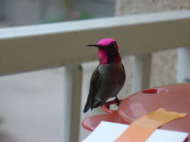
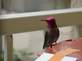
My hummingbird video


I made a hummingbird video to test out the 3d features myself. The embedded video below does not show the 3D interface. You must go to the YouTube page itself to see the full range of possibilities. Grab a pair of red/blue 3D glasses if you have one.


Remember to check out the original movie to see all of the 3D viewing options.

This hummingbird movie could be improved in several ways
  1. The left side is out of focus. I meant to set the focus for both cameras to 15 cm, but it looks like the focal length of the left eye was set too short.
  2. The sound doesn't seem to work. I plugged in a microphone, and selected the one audio option that was available in AmCap, but I don't hear any sound in the video. This needs to be investigated.
  3. I should register Stereoscopic Multiplexer, to avoid those watermarks on the video. It will cost about $90. Ouch.
  4. It would be good to get more light on the bird. Unfortunately, the sun won't shine on my patio until summer.
  5. The format is Left-Right (parallel), but the emerging YouTube standard is Right-Left (cross-eye), so I should use the Right-Left convention in the future. Plus I have an easier time free-viewing cross-eye, so it will be more convenient for me when viewing embedded videos like the one above. I used the YouTube tag "yt3d:swap=true" to correct for this inversion.

Other YouTube 3D videos


The following are examples of other stereoscopic videos on YouTube, created by others:

This so-called biodiversity documentary contains professional-quality footage of domesticated ducks, geese, and honeybees in India. The narration is done with a top-quality computer generated voice. The voice is only slightly creepy.


This next one is taken with a helmet camera. It is interesting and entertaining. It includes some cityscape images. Unfortunately, a cityscape shows little depth when using a normal human interpupillary distance of 60 mm or so. Hyperstereo might have been nice here.


There are many many other stereoscopic videos on YouTube. Search for "yt3d" on YouTube.

How I made the hummingbird video


I created my hummingbird video using two USB pen cameras. So I could get the two cameras as close as possible. This setup is suited for small, close subjects, such as hummingbirds. Because the two cameras are only 14 mm apart, as opposed to the 60 mm separation of human eyes, my setup yields a view as seen by another hummingbird, rather than what would be seen by a person. This is called hypostereo.

Two USB pen cameras and a portable netbook style computer are the basis of my stereoscopic video system. I created a custom bracket for the cameras so I can mount them on a tripod. The bracket is carefully shaped to compensate for the idiosyncrasies of these particular cameras. These very cheap cameras do not point in exactly the same direction.


The narrow 14 mm distance between the camera lenses is crucial to producing a subtle 3D effect with small close subjects such as the hummingbird. I chose these pen cameras because this form factor permits the smallest camera separation I could find.


Here is a shot of the whole setup prepared to take hummingbird videos.

Saturday, August 22, 2009

Tk 8.5 is better than wxWidgets on Windows

UPDATE: It appears this issue might be fixed in a future release of wxwidgets.

I frequently write computer programs with graphical user interfaces ("GUI"s). I insist that the interfaces look good on Windows, Mac, and Linux computers. By "good", I mean that the widgets (the buttons, sliders, and what-not), look exactly like those found on most other applications developed specifically for that particular platform. For example, buttons and progress bars on Mac must have that clear blue "Aqua" look.

There are several programming tool kits which help to create native-looking user interfaces on multiple platforms. The three platforms I pay particular attention to are Windows, Mac, and Linux. Cross-platform GUI tool kits include wxWidgets, Tk, and Java Swing. This post documents the failure of wxWidgets and Java Swing to respect Windows font sizes.

Look at the following picture to see the failure of wx and Java to respect the Windows font sizes. From left to right, the test programs are in Visual Basic, python/Tk, python/wx, and Java Swing.


wxWidgets looks nice in some cases, but it has some ways to go to support native look and feel on Windows. I am working on several Windows XP systems, on which I routinely select "Large Fonts" in my desktop preferences. wxWidgets does not respect those preferences.

To see the difference, first set extra large fonts on your desktop:

Far click desktop -> Properties -> Appearance -> Font Size -> Extra Large Fonts

Next, write an application using wxWidgets and test whether it respects your font choice. I didn't think so.

If it's any consolation, Java doesn't respect the Windows font size either.

If you want to use a cross-platform widget tool kit, and your definition of "cross-platform" includes Windows, my recommendation is to use Tk 8.5.

The table below summarizes the results for the four test programs I wrote:


GUI tool kits on Windows
Tool KitNative look-and-feel?Respects font size?
Visual basicNo(!)Yes
Tk 8.5YesYes
wx 2.8.10YesNo
Java 1.6.0YesNo


Below are the test programs I wrote to create the windows shown at the beginning of this post.


  • Visual Basic

    ' "Hello, World!" program in Visual Basic.
    Module Hello
    Sub Main()
    MsgBox("Hello, World! (VB)") ' Display message on computer screen.
    End Sub
    End Module


  • Tk 8.5 (tkinter in python 3.1)

    # Note - requires python 3.1 for ttk 8.5 support
    import tkinter as tk
    import tkinter.ttk as ttk

    root = tk.Tk()
    padding = 10
    panel = ttk.Frame(root, padding=padding).pack()
    label = ttk.Label(panel, text="Hello, World! (Tk)")
    label.pack(padx=padding, pady=padding)
    button = ttk.Button(panel, text="Hello", default="active")
    button.pack(padx=padding, pady=padding)
    root.mainloop()


  • wx 2.8.10 (in python 2.6 with wxpython)

    import wx

    padding = 10
    app = wx.App(0)
    frame = wx.Frame(None, -1, "Hello")
    panel = wx.Panel(frame)
    sizer = wx.BoxSizer(wx.VERTICAL)
    panel.SetSizer(sizer)
    text = wx.StaticText(panel, -1, "Hello, World! (wx)")
    sizer.Add(text, 0, wx.ALL, padding)
    button = wx.Button(panel, -1, "Hello")
    sizer.Add(button, 0, wx.ALL, padding)
    frame.Centre()
    frame.Show(True)
    app.MainLoop()


  • Java swing 1.6.0

    import javax.swing.*;
    import java.awt.Dimension;

    public class HelloWorldFrame extends JFrame
    {
    public static void main(String args[])
    {
    new HelloWorldFrame();
    }
    HelloWorldFrame()
    {
    try {
    UIManager.setLookAndFeel(UIManager.getSystemLookAndFeelClassName());
    } catch(Exception e) {}
    JPanel panel = new JPanel();
    add(panel);
    panel.setLayout(new BoxLayout(panel, BoxLayout.PAGE_AXIS));
    panel.setBorder(BorderFactory.createEmptyBorder(10,10,10,10));
    JLabel label = new JLabel("Hello, World! (java)");
    panel.add(label);
    panel.add(Box.createRigidArea(new Dimension(0, 10)));
    JButton button = new JButton("Hello");
    panel.add(button);
    pack();
    setVisible(true);
    }
    }


The wx bug tracker has had a couple of bug reports for this problem, one open for five years. Somehow I doubt they are itching to fix this problem.

The Tk source code that sets the windows correctly appears to be near line 418 of file win/tkWinFont.c in the Tk source code:


if (SystemParametersInfo(SPI_GETNONCLIENTMETRICS,
sizeof(ncMetrics), &ncMetrics, 0)) {
CreateNamedSystemLogFont(interp, tkwin, "TkDefaultFont",
&ncMetrics.lfMessageFont);
CreateNamedSystemLogFont(interp, tkwin, "TkHeadingFont",
&ncMetrics.lfMessageFont);
CreateNamedSystemLogFont(interp, tkwin, "TkTextFont",
&ncMetrics.lfMessageFont);
CreateNamedSystemLogFont(interp, tkwin, "TkMenuFont",
&ncMetrics.lfMenuFont);
CreateNamedSystemLogFont(interp, tkwin, "TkTooltipFont",
&ncMetrics.lfStatusFont);
CreateNamedSystemLogFont(interp, tkwin, "TkCaptionFont",
&ncMetrics.lfCaptionFont);
CreateNamedSystemLogFont(interp, tkwin, "TkSmallCaptionFont",
&ncMetrics.lfSmCaptionFont);
}


The wx source code has similar code in a few locations. But it appears that this technique may be only used for menu fonts and message dialog fonts.

The main problem might be that the method wxGetCCDefaultFont() in the wx source code uses SPI_GETINCONTITLELOGFONT instead of SPI_GETNONCLIENTMETRICS.

Microsoft has documentation for the NONCLIENTMETRICS data structure.

Even if the wx authors fix this today, I fear it will be a long time before the change trickles down into a wxPython release.

Saturday, August 15, 2009

Write your own stereoscopic 3D program using nVidia's "consumer" stereo driver


I have always been a fan of nVidia graphics boards because of their support for 3D stereoscopic games. But the "consumer level" (non-Quadro) stereoscopic drivers only seem to work with games. I have always wondered how to create my own applications that can use the stereoscopic drivers on less-expensive gaming video boards. Now I have found a way.

The "consumer" stereoscopic driver from nVidia only works with "full screen" games. When I started experimenting with OpenGL, I assumed that using the call "glutFullScreen()" might be enough to get the stereoscopic drivers to kick in. But it is not.

The trick is to use the glutEnterGameMode() call. I did a lot of searching on the internet, and nowhere is it mentioned that you must call glutEnterGameMode() to get the nVidia "consumer level" stereoscopic drivers to work. That is why I am sharing this blog post.

My working system is on Windows XP. I am uncertain if this approach will work with Windows Vista/7. I am a bit concerned because nVidia seems to be selling a hardware stereoscopic product these days. I am worried that my custom stereoscopic theater, which uses a pair of polarized video projectors, won't work if I upgrade my Windows version.

Here is how you can do it too, on Windows XP:
  1. Ensure you have a supported nVidia graphics board in your computer. See the stereoscopic driver users' guide for more details.
  2. Get the stereoscopic driver from nVidia. The most recent version (91.31) released for Windows XP is from 2006. That is the one I am using. Consult this driver guide for more details.
  3. Install Python 2.6 and PyOpenGL version 3.0.0, so you can conveniently create OpenGL programs in python.
  4. Familiarize yourself with OpenGL programming. I got started by following the examples of the "red book", the OpenGL Programming Guide.
  5. Study my example program, below, to learn how to call glutGameModeString() and glutEnterGameMode().
Below is the text of a complete working python program that works with the nVidia "consumer level" stereoscopic driver on my Windows XP computer. (The stereoscopic presentation only appears in the full screen gaming mode):

Modify the display() method and the animate() method to show whatever you want!

#!/cygdrive/c/Python26/python

from OpenGL.GL import *
from OpenGL.GLU import *
from OpenGL.GLUT import *
import sys


def do_nothing(*args):
"""
Empty method for glutDisplayFunc during risky transition to game mode.
"""
pass


class HelloOpenGL(object):
"""
Creates a rotating wire frame cube using OpenGL.

Pressing the "f" key toggles full screen game mode.
This full screen mode works with nVidia stereoscopic
driver for Windows XP.
"""
def __init__(self):
self.animation_interval = 100 # milliseconds
self.rotation_angle = 0.0 # degrees, starting point
glutInit("Cube.py")
glutInitDisplayMode(GLUT_RGBA | GLUT_DOUBLE | GLUT_DEPTH)
glEnable(GL_DEPTH_TEST)
glutInitWindowSize(200, 200)
# Remember window id for when we return from game mode.
self.window_id = glutCreateWindow('Wire Cube')
self.initialize_gl_context()
# glutTimerFunc remains when GL context is replaced,
# so it does not go into self.initialize_gl_context()
glutTimerFunc(self.animation_interval, self.animate, 1)
glutMainLoop() # never returns

def clear_gl_callbacks(self):
"""
Set inoccuous callbacks during times when no valid context may be available.
"""
glutDisplayFunc(do_nothing)
glutMotionFunc(None)
glutKeyboardFunc(None)

def initialize_gl_context(self):
"""
When switching between full-screen and windowed modes,
initialize_gl_context() reinitializes state.
"""
glClearColor(0.5,0.5,0.5,0.0)
glutDisplayFunc(self.display)
# glutPassiveMotionFunc(self.mouse_motion)
glutMotionFunc(self.mouse_motion)
glutKeyboardFunc(self.keypress)
# establish the projection matrix (perspective)
glMatrixMode(GL_PROJECTION)
glLoadIdentity()
x,y,width,height = glGetDoublev(GL_VIEWPORT)
gluPerspective(
45, # field of view in degrees
width/float(height or 1), # aspect ratio
.25, # near clipping plane
200, # far clipping plane
)

def start_game_mode(self):
if glutGameModeGet(GLUT_GAME_MODE_ACTIVE):
return # already in game mode
glutGameModeString("800x600:16@60")
if glutGameModeGet(GLUT_GAME_MODE_POSSIBLE):
self.clear_gl_callbacks()
glutEnterGameMode()
self.initialize_gl_context()

def start_windowed_mode(self):
if glutGameModeGet(GLUT_GAME_MODE_ACTIVE):
self.clear_gl_callbacks()
glutLeaveGameMode()
# Remember the window we created at start up?
glutSetWindow(self.window_id)
self.initialize_gl_context()

def display(self):
"""
"display()" method is called every time OpenGL updates the display.
"""
# Erase the old image
glClear(GL_COLOR_BUFFER_BIT | GL_DEPTH_BUFFER_BIT)
# Modelview must be set before geometry is sent
# or else crash when entering stereoscopic mode.
glMatrixMode(GL_MODELVIEW)
glLoadIdentity()
gluLookAt(
0,-0.5,5, # eyepoint
0,0,0, # center-of-view
0,1,0, # up-vector
)
# Rotate about the origin as animation progresses
glRotate(self.rotation_angle, 0, 1, 0)
glPushMatrix()
try:
# Draw the cube
glutWireCube(2.0)
finally:
glPopMatrix()
glutSwapBuffers()

def mouse_motion(self, x, y):
pass

def keypress(self, key, x, y):
if key == '\033':
# Escape key leaves full screen mode
if glutGameModeGet(GLUT_GAME_MODE_ACTIVE):
self.start_windowed_mode()
elif key == "f":
# "f" key toggle full screen and windowed mode.
if glutGameModeGet(GLUT_GAME_MODE_ACTIVE):
self.start_windowed_mode()
else:
self.start_game_mode()

def animate(self, value):
"""
Periodically change the rotation angle for the cube animation.

This animate method() is called as a glutTimerFunc().
"""
self.rotation_angle += 1.0
while self.rotation_angle > 360.0:
self.rotation_angle -= 360.0
glutPostRedisplay()
# Be sure to come back for more
glutTimerFunc(self.animation_interval, self.animate, value+1)


# Run the HelloOpenGL application when this script is run directly.
if (__name__ == '__main__'):
HelloOpenGL()

Friday, July 13, 2007

Phantom cell phone vibrations

I have had a cell phone (Treo 680) for about 8 months. I keep it in my front right pants pocket. I always have it set to "vibrate". Lately, my leg has begun to vibrate right where the phone is, causing me to think that the phone is ringing.

It's really creepy.

One time I moved the cell phone away from my leg, but I could still feel the vibration in my leg. I could feel my leg actually vibrating with my hand. I couldn't get it to stop. My leg kept on "ringing" occasionally for quite some time. I have started keeping the phone in a different pocket.

Judging by the number of "I thought it was just me..." responses in a forum I found online, this is a surprisingly common phenomenon. According to this article, it happens when you are expecting a call. I don't get very many calls, so it does not take much!

Yikes!

Who's calling? Is it your leg or your cell phone? — JSCMS
Good vibrations? Bad? None at all? - USATODAY.com
Digg - Have You Noticed the Cell Phone "Phantom Vibration Syndrome"?

Monday, July 09, 2007

Using rxvt in cygwin

I don't like the default cygwin bash window.

To get a nice terminal in cygwin, I have been typing "rxvt" from the cygwin bash shell for years. After several previous abortive attempts, I have finally succeeded in creating a clickable icon that directly launches a nice rxvt (xterm-like) terminal window under Windows.

The solution I found is described at http://freemode.net/archives/000121.html.


I made a few modifications, because I like a larger font, and the batch file did not work for me without modification.

My ~/.Xdefaults file looks like this now:

! ~/.Xdefaults - X default resource settings
Rxvt*geometry: 120x40
Rxvt*background: #000020
Rxvt*foreground: #ffffbf
!Rxvt*borderColor: Blue
!Rxvt*scrollColor: Blue
!Rxvt*troughColor: Gray
Rxvt*scrollBar: True
Rxvt*scrollBar_right: True
! Rxvt*font: Lucida Console-12
Rxvt*font: fixedsys
Rxvt*SaveLines: 10000
Rxvt*loginShell: True
! VIM-like colors
Rxvt*color0: #000000
Rxvt*color1: #FFFFFF
Rxvt*color2: #00A800
Rxvt*color3: #FFFF00
Rxvt*color4: #0000A8
Rxvt*color5: #A800A8
Rxvt*color6: #00A8A8
Rxvt*color7: #D8D8D8
Rxvt*color8: #000000
Rxvt*color9: #FFFFFF
Rxvt*color10: #00A800
Rxvt*color11: #FFFF00
Rxvt*color12: #0000A8
Rxvt*color13: #A800A8
Rxvt*color14: #00A8A8
Rxvt*color15: #D8D8D8
! eof


My replacement for the default "cygwin.bat", which I call "cygwin-rxvt.bat" is as follows:

@echo off
C:
chdir C:\cygwin\bin
set EDITOR=vi
set VISUAL=vi
set CYGWIN=codepage:oem tty binmode title
set HOME=\cygwin\home\spud
rxvt -e /bin/tcsh -l


You will notice that I use tcsh rather than bash. Yes, yes, I know that hard-core UNIX geeks disdain tcsh and only use bash. Shut up. I don't care about you.

Finally, I use a simple prompt with tcsh, which has the side effect of setting the title bar for xterm-like terminals (including rxvt). I add the following line to my .tcshrc file:

set prompt="%{\033]0;%~%L\007%}\[%h\]> "

Sunday, April 22, 2007

Extracting the magnitude component of an image Fourier transform

New result!

I finally succeeded in extracting the magnitude component of the image Fourier transform (shown at right).


Recapping the story so far

I previously created a picture of a bird, and a slightly translated version of the same image. I intend to use these images to test ideas about using the Fourier transform to automatically align pairs of images to create aligned stereoscopic pairs.

The input images, show in the previous post, are summarized below:


Original image


Translated version of the original image, for testing my hypothesis.


Fourier transform of original, masked image.


Fourier transform of translated, masked image


I took the plunge and learned to write a filter using the pbmplus environment (see previous post). Here is the program as I wrote and used it for this post:


The new PGM filter I made

I understand that it is tedious to mix GIMP and PBM tools in an image processing pipeline. Perhaps I will port the FFT image processing to PBM later...

What follows next is C language source code I just now wrote for a new image filter in the PBMPlus or NetPBM image processing tool kit:

/* pgm_fourier_recast.c - read a portable graymap produced by the
** GIMP Fourier plug-in, and extract magnitude and phase components
**
** Copyright (C) 2007 by biospud@blogger.com
**
** Permission to use, copy, modify, and distribute this software and its
** documentation for any purpose and without fee is hereby granted, provided
** that the above copyright notice appear in all copies and that both that
** copyright notice and this permission notice appear in supporting
** documentation. This software is provided "as is" without express or
** implied warranty.
*/


/*
** 1) Place source file pgm_fourier_recast.c in directory with working build of netpbm/editor
** 2) Add "pgm_fourier_recast" to list of files in Makefile
** 3) "make pgm_fourier_recast" from netpbm/editor directory
*/


#include <stdio.h>
#include <math.h>
#include "pgm.h"

typedef struct pgm_image_struct {
int height;
int width;
gray maximumValue;
gray** data;
} PgmImage;

PgmImage getInputImage( int argc, char *argv[] );
PgmImage convertFourierToPhaseMagnitude(PgmImage inputImage);
void writeImageAndQuit(PgmImage outputImage);
double gimpFourierPixelToDouble(PgmImage image, int x, int y);
double getNormalizationFactor(PgmImage image, int x, int y);
gray doubleToGimpFourierPixel(double value, PgmImage image, int x, int y);

int main( int argc, char *argv[] )
{
PgmImage inputImage;
PgmImage outputImage;

inputImage = getInputImage(argc, argv);
outputImage = convertFourierToPhaseMagnitude(inputImage);
writeImageAndQuit(outputImage);
}

PgmImage getInputImage( int argc, char *argv[] ) {
const char* const usage = "[pgmfile]";
int argn;
FILE* inputFile;

PgmImage answer;

pgm_init( &argc, argv );

argn = 1;

if ( argn < argc ) {
inputFile = pm_openr( argv[argn] );
++argn;
} else {
inputFile = stdin;
}

if ( argn != argc )
pm_usage( usage );

answer.data = pgm_readpgm(
inputFile,
&answer.width,
&answer.height,
&answer.maximumValue
);

pm_close( inputFile );

return answer;
}

double gimpFourierPixelToDouble(PgmImage image, int x, int y) {
/*
** based on source code at
** http://people.via.ecp.fr/~remi/soft/gimp/gimp_plugin_en.php3
*/


gray pixel = image.data[x][y];

/*
** renormalize
** from (range 0 -> 255)
** to range (-128 -> +127),
*/

double d128 = (double)(pixel) - 128.0; /* double128() */

double bounded = (d128 / 128.0); /* unboost() */
double unboosted0 = 160 * (bounded * bounded); /* unboost() */
double unboosted = d128 > 0 ? unboosted0 : -unboosted0; /* unboost() */

double answer = unboosted / getNormalizationFactor(image, x, y);

return answer;
}

/* Normalization factor that corrects scale of Fourier transform
** pixel based upon distance from origin
*/

double getNormalizationFactor(PgmImage image, int x, int y) {
/*
** based on source code at
** http://people.via.ecp.fr/~remi/soft/gimp/gimp_plugin_en.php3
*/

double cx = (double)abs(x - (image.width + 1)/2 + 1);
double cy = (double)abs(y - (image.height + 1)/2 + 1);
double energy = (sqrt(cx) + sqrt(cy));
return energy*energy;
}

gray doubleToGimpFourierPixel(double value, PgmImage image, int x, int y) {

double normalized = value * getNormalizationFactor(image, x, y);
double bounded = fabs( normalized / 160.0 );
double boosted0 = 128.0 * sqrt (bounded);
double boosted = (value > 0) ? boosted0 : -boosted0;

/*
** renormalize
** from range (-128 -> +127),
** to (range 0 -> 255)
*/

int answer = (int)boosted + 128;
if (answer >= 255) return 255;
if (answer <= 0) return 0;
return answer;
}

PgmImage convertFourierToPhaseMagnitude(PgmImage inputImage) {
PgmImage answer;
int outRows = inputImage.height;
int outCols = inputImage.width;
int row, col;

double realDouble, imaginaryDouble;
double magnitudeDouble, phaseDouble;
gray realPixel, imaginaryPixel;
gray magnitudePixel, phasePixel;

int doUsePhase = 0;

answer.height = outRows;
answer.width = outCols;
answer.maximumValue = inputImage.maximumValue;
answer.data = pgm_allocarray( outCols, outRows );

for ( row = 0; row < outRows; ++row ) {
for ( col = 0; col < outCols; col += 2) {
/* get pixel values from image */
realPixel = inputImage.data[row][col];
imaginaryPixel = inputImage.data[row][col + 1];

/* convert to doubles */
realDouble = gimpFourierPixelToDouble(inputImage, row, col);
imaginaryDouble = gimpFourierPixelToDouble(inputImage, row, col);

/* convert real/imaginary to magnitude/phase */
magnitudeDouble = sqrt(
realDouble * realDouble +
imaginaryDouble * imaginaryDouble
);

/* convert to pixel values */
magnitudePixel = doubleToGimpFourierPixel(
magnitudeDouble,
inputImage, row, col
);

if (doUsePhase) {
phaseDouble = atan2(imaginaryDouble, realDouble);

phasePixel = (int)(256.0 * phaseDouble / (2.0 * 3.14159));
while (phasePixel > 255) phasePixel -= 256;
while (phasePixel < 0) phasePixel += 256;
}

/*
i1 = inputImage.data[row][col];
v = gimpFourierPixelToDouble(inputImage, row, col);
i2 = doubleToGimpFourierPixel(v, inputImage, row, col);
printf("%.3g\t%.3g\t%.3g\t%.3g\n",
realDouble, imaginaryDouble, magnitudeDouble, phaseDouble);
*/


answer.data[row][col] = magnitudePixel;

if (doUsePhase)
answer.data[row][col + 1] = phasePixel;
else
answer.data[row][col + 1] = magnitudePixel;

}
}

return answer;
}

void writeImageAndQuit(PgmImage outputImage) {
/* Write resulting image */
pgm_writepgm(
stdout,
outputImage.data,
outputImage.width,
outputImage.height,
outputImage.maximumValue,
0
);

/* and clean up */
pm_close( stdout );
pgm_freearray(
outputImage.data,
outputImage.height
);

exit( 0 );
}


Original vs. translated images in Fourier magnitude space:

Phew! After writing this filter, I created the following "magnitude only" versions of the test images:


Original: Magnitude component of Fourier transform of original image


Translated: Magnitude component of Fourier transform of translated image

A superficial look suggests that the magnitude component is in fact very similar between the two images. But for automation, I need a quantitative measure to decide how similar two images are. More next time...

Thursday, April 19, 2007

Testing my Fourier transform hypothesis

In the past few posts I have repeatedly assumed that the magnitude component of the Fourier transform of an image will be relatively unchanged when the original image is translated vertically and/or horizontally. My next task should be either prove or disprove this hypothesis before going much further.

Let's start with two gray-scale images that differ only in horizontal alignment for testing. If my intuition is correct, the magnitude portion of the Fourier transform should differ only slightly between the two images.

I downloaded and installed NetPBM, to facilitate command line processing of images. I suspect that it will be easier for me to write new pbm filters than to write GIMP plug-ins.

One infuriating thing about NetPBM is that one of the maintainers has destroyed many of the original man pages in an effort to "simplify" the distribution. I genuinely appreciate this dude taking on the responsibility to maintain the code, but this one horrible documentation decision has caused me to curse out loud many times in the past several years. My feelings are neatly summed up by the observations of another user on the netbsd packaging discussion list:


"...I want the manual as released with the code I'm using, no changes after the fact. Release your manuals, don't blog them. it is *IMPOSSIBLE* for me to get that manual, no matter how many hoops I jump through, because you cannot (as they suggest) 'wget' an old version of the manual, one which still has manual pages instead of links to other non-Netpbm projects featured on the top page, one which has actual documentation for pnmscale rather than a three-page rant about why I should switch to Netpam..."


Hear hear.

In any case, here is a visual overview of the experiment set-up:


Original image

One thing I will need is a method to compare how similar two images are. As a control, I will be comparing the original image to itself.


Translated version of the original image, for testing my hypothesis.

If I am right about the Fourier transform, the magnitudes of the Fourier transform will be almost the same between the original image and the translated one. This will simulate the comparison of stereo pairs that do not perfectly line up.


Gray version of the translated image

To simplify the analysis, I created a gray-scale version of the images, so the issue of the color channels does not complicate the analysis.


The mask I used to "remove" the edges of the images

Recall from my earlier posting that the blurry circle mask is used to reduce edge artifacts in the Fourier transform.


Apply circle mask to untranslated image


Masked version of translated image

Finally, create the two Fourier transforms, one for the untranslated image and one for the translated image:


Fourier transform of original, masked image.


Fourier transform of translated, masked image

Next I need to extract the magnitudes of the Fourier transforms and compute the similarities between the images. I have some ideas of how to do this, but it will require more work. I expect that the PBM tools will come in handy here. More next time...

Sunday, April 15, 2007

Investigating the GIMP Fourier transform

In my previous post I began to work up how we might use the Fourier transform to help align two images that form a 3D stereoscopic image pair.

A more detailed investigation reveals that we need to ask a few more questions.

I sort of understand what the Fourier transform means for scalar data. But in an image, there are three different channels of color information, usually decomposed in one of two ways.

Two different representations of three-dimensional color data in an image pixel:
  1. red, green, and blue (RGB), or alternatively as
  2. hue, saturation, and brightness. (HSV)
For any ONE of these channels (e.g. "red"), I can kind of understand what the Fourier transform is. The transform for any single channel should result in a complex number in each pixel of the transform. Complex numbers have two components. These two components of a complex number can be represented in at least two different ways.

Two different representations of a two dimensional complex number:
  1. Real component and Imaginary component
  2. Magnitude and phase


Two ways of representing a complex number: magnitude/phase and real/imaginary

The bottom line here is that is seems to me that the Fourier transform should have twice as much data as the original image, since the Fourier transform takes regular real numbers, and generates complex numbers. So a regular 3-channel image should create a Fourier transform with 6 channels. So what exactly is in the Fourier transform generated by the GIMP plug-in?

Unfortunately the documentation for the plug-in is in French, and I have not studied French since the mid-1970s.

Understanding how the transform data are represented is especially important at this point for two reasons:
  1. The whole trick of using the Fourier transform to ignore the horizontal/vertical translation component requires that we use only the magnitude of the complex numbers (which does not depend upon the image translation), and ignore the phase component (which depends exquisitely upon the image translation).
  2. Where are the six channels of data that should be coming from the Fourier transform?
So we need to determine whether the complex Fourier transform is stored as real/imaginary components, or if it is stored as magnitude/phase components. More fundamentally, we need to know how six channels of information are being stored in the seemingly 3 or 4 channeled image data (transparency can provide an additional channel).

I did some experimentation and determined that the red channel of the Fourier transform corresponds to the red channel of the original image, etc. Excellent.

Further, the French documentation is surprisingly intelligible when filtered through AltaVista babelfish. I still don't quite understand all of the details, but it appears that the complex values are stored in pairs of subsequent pixels, representing the logarithm of the real component, followed by the logarithm of the imaginary component. This is bad news. I want the magnitude of the complex number, which is equal to the square root of the sum of the squares of the real and imaginary components (using Pythagoras' theorem). It will be hairy to extract that information. So I need to either a) find another Fourier transform image filter, b) write a GIMP plug-in that further processes these Fourier transform images, c) think of some other trick, or d) abandon this project.

By the way, if you read the English translation of the French documentation, there is a good explanation of why, near the end of the article, he compares his simulated image to a "moose". It turns out that the French word for "moose" is "orignal", while the French word for "original" is "original". The author made a typo, misspelling "original" to accidentally type another actual French word. Thus his spell-checker did not catch it. I believe he meant to say that the simulated image resembles the original image, not that it resembles a moose. Or not. Who knows?

I will cogitate some more on what to do next. More next time...

Use of Fourier transform in aligning stereoscopic image pairs

In my previous post, I wondered how to begin to determine parameters for aligning two images, when no other parameters have yet been determined.

One concept that can help is the Fourier transform. The Fourier transform can be used to eliminate the vertical and horizontal alignment components from the analysis. Thus we should be able to determine certain parameters, such as scale and rotation, without having to first solve the vertical and horizontal alignment problem.

The GIMP image tool has a plug-in that permits computation of the Fourier transform of an image. (Presumably Photoshop has a similar tool).


Left bird image
The unmodified left-eye view from yesterday


Fourier transform of left eye bird imageFourier transform of the same bird image, as generated by the GIMP plug in.

Believe it or not, the Fourier transform contains all of the information necessary to reconstruct the original image.

It is difficult for the human eye to make sense of the Fourier transform image. The two largest features are a big vertical stripe down the middle, and a horizontal stripe across the center. Unfortunately, these features are a BAD thing. They show that the Fourier transform is dominated by something I don't care about.

What features of the original image have strong horizontal and vertical components, causing the primary features of the Fourier transform? This is perhaps a subtle point: the edges of the image cause these features. This is a problem. If we want to use the Fourier transform to detect the relative rotation between two images, we cannot have the edges of the image dominating the Fourier transform. The vertical and horizontal edges of the images will be used to form the rotational alignment, and no rotation will occur.

The solution is to remove the edges of the image before taking the Fourier transform. But how do you remove the edges of an image? Like this:

Bird image with "edges removed"


I created a circular mask for the imtage, so that it would be radially symmetric, thus minimizing image shape artifacts in lining up the relative rotation of two images. Further, I made the mask a blurry circle, figuring that a blurry edge would have more localized effects on only the low-resolution region of the Fourier transform. The new Fourier transform of the "edge-removed" version of the bird is much smoother:


Fourier transform of edge-removed bird image

It now becomes clear that many of the other primary features of that initial Fourier transform were also "ringing" artifacts related to the edge effect. To sum up the results so far:
  1. The Fourier transform looks like it might theoretically be a useful tool for determining the scale and/or rotation relationship between two images, without needing to first determine the translational components.
  2. If we end up using the Fourier transform in this way, we should include a pre-processing step in which we make a blurry-edged circular version of the two images to be compared.
This is a small amount of progress, but I feel it will probably pay off. More next time...


Toward automatic alignment of stereoscopic image pairs

When aligning the two images of a stereoscopic pair, we wish to determine the following parameters:
  1. Scale: The relative scale between the two images. Usually close to 1.0, but might vary if two cameras were used with slightly different zoom or distance.
  2. Rotation: There may be a small relative rotation between the two images, either clockwise or counterclockwise. This can be tedious to determine manually.
  3. Eye axis: The direction relating the left eye to the right eye is usually left to right, but might be off by a small angle. For various special ad hoc stereoscopic techniques, such as 3D photos of the moon, determining this direction is very important. It is tedious and imprecise to determine this axis manually. Most folks just assume that the eye axis is perfectly horizontal and move on.
  4. Translation: Alignment in the left/right direction and in the up/down direction.
    • Up/down: There is a single clear value for the correct alignment in the up/down direction, perpendicular to the eye axis. This value can be determined manually, but should be amenable to automatic determination as well.
    • Left/right: Alignment along the eye-axis varies from pixel to pixel depending upon the depth of the subject. This is how 3D photos work. Determining left/right alignment may be the hardest part to automate.
  5. Brightness and color balance: Especially when the two images are taken with two cameras, as in my set-up, the two images may differ in brightness and color balance. These differences should be corrected before generating a final stereo pair.
How can you determine any of these relationships between two images when you don't know the values of the other parameters? This can be a tricky problem. And it probably requires some tricky solutions.


Left bird imageRight bird image
The images above are a typical example of a raw stereoscopic pair. The two images obviously differ in color balance, vertical alignment, and horizontal alignment.

I will attempt to attack the problem of determining each parameter in turn, in subsequent posts.

Saturday, April 07, 2007

Hummingbird with tongue hanging out

Juvenile male Anna's hummingbird (Calypte anna) tasting the air

Just now I got a nice photo of a hummingbird sticking his tongue out (click bird for larger image). Notice the fine silvery tongue extending beyond the tip of the beak. This photo represents about the limit of image resolution I will be able to acheive with my current optical set-up. I am pretty happy with this resolution. Unfortunately, in this particular shot the companion camera image was out of focus, so there will be no stereoscopic version of this tongue shot forthcoming. (Not that I have yet created any 3D photos good enough to post!)

Today's shoot was my first success at getting decent photos using mirrors. Previously my mirror photos were too blurry and displayed second reflection artifacts. Today I used first surface mirrors mounted more securely. That seems to have done the trick! Now perhaps I will be able to get stereoscopic photos with a smaller interpupilary separation. With today's mirror setup, the separation is about 50 mm, which is still sort of big at this 400 mm distance. I don't know how I can get it smaller though.

Wednesday, April 04, 2007

What a coincidence! Here's one with a full purple head now!

Deep magenta throat and crown of male Anna's hummingbird (Calypte anna)

(click bird for larger image)

Yesterday I said that the male Anna's hummingbird can have a completely magenta head. On cue, my charming bride captured this image of a male in full display. I guess the male in the earlier pictures is either a hybrid species, a juvenile, or just a mutant. Perhaps it helps that the sky was overcast today.

Tuesday, April 03, 2007

Male Anna's hummingbird at even higher resolution.

Male Anna's Hummingbird (Calypte anna) in repose at feeder

My beautiful wife captured our best hummingbird pictures yet this morning (click bird for higher resolution view). Notice the fine detail in the feathers. This male Anna's hummingbird, like many male hummingbirds, has a bright red neck when viewed from certain angles. I am uncertain whether this depends upon the orientation of the feathers, the orientation of the sun, the orientation of the person viewing, or some combination of those three. In any case, the geometry of this bird was right to show the red throat. From other angles, the throat of the male appears dark or black. (The throat of the female is much paler. See some of our previous photos in older posts).

This species, Anna's hummingbird (Calypte anna), is the only hummingbird species in which the crown (top of the head) of the male can also appear crimson (in addition to the throat). If you look carefully at the photo above, you can see a few reddish feathers on the head. Google image search for "Anna's Hummingbird" and you will find many images of male birds in which the entire head glows with a brilliant magenta color. You have to view the bird from just the right angle to get that effect.

On the lower left of this bird's throat is a region that is yellow-green, almost the exact complementary (opposite) color to the red-magenta seen on the rest of the throat. I suspect that the complementary color viewed from a different angle is no coincidence. It reminds me of the cytological stain eosin, which is colored red-magenta when you view light through the solution, but is yellow-olive when you view light reflected off of the solution's surface. Eosin is one of the important stains used in Pap smears, and many other important microscopic tissue staining methods.

Monday, April 02, 2007

Today's hummingbird pictures

What is that yellow material on the male hummingbird's beak? Pollen?


Notice the fluffy feathers on this male hummingbird's underside

Saturday, March 24, 2007

First clear Danio photo


I just took this picture of a Danio (zebrafish) in our fish tank. I used a flash, so I had to take the picture from an angle so that I didn't just take a picture of the reflection of the flash. As with the hummingbird pictures, I took this with a two camera set up, so that I can create stereoscopic pictures. Once I get better at composing the stereo pairs, I will start posting 3D pictures. It is possible that I will make 3D versions of these same pictures that I am posting now.

Sunday, March 18, 2007

New hummingbird pictures.


We started filling our hummingbird feeder about two weeks ago. I think we already have a nesting pair settling down nearby. I got some nice pictures this morning when the sun was shining on the feeder. Shown here is a female.

Wednesday, August 02, 2006

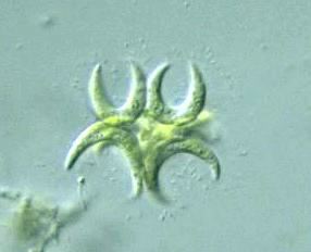
Selenastrum capricornutum algae in our aquarium

SelenastrumWe started a ten gallon fish tank in our apartment four weeks ago.

For the first three weeks, our aquarium went through the standard series of nitrogen compound crises that a new tank experiences before it is "cycled", as the fish tank enthusiasts say. During those three weeks, our tank water was crystal clear.

About one week ago, our nitrite levels fell abruptly to zero, indicating that our "biological filter" was now colonized by all of the bacteria needed to complete the nitrogen cycle. As soon as the nitrite levels fell, algae began to grow. The water in our tank is quite green.

I placed a drop of our tank water on a microscope slide and viewed the contents at 150X with an inexpensive microscope I obtained in the 1970s. There I found green U-shaped algae with pointy ends. After a bit of google image searching, I conclude that the species of algae is Selenastrum capricornutum, or Selenastrum gracile.

It's fun to identify the organisms in your home. I recommend it.

Other species I have identified in my home:
  1. Homo sapiens notsosapiensis
  2. Danio rerio (zebra danios)
  3. Palaemonetes kadakensis (ghost shrimp)

Monday, April 03, 2006

Const correctness and duck typing

I am a big fan of "const correctness" when programming in C++. It permits me to be a lazier programmer, but this is a good thing. It permits me to be a lazier programmer in the same way that these other language features do:
  • Using local variables instead of global variables
  • Using formal loop constructs like "for", "while", and "do", instead of "GOTO"
  • Using iterators instead of looping with "for", "while", and "do"
  • Program to interfaces instead of implementations
It is possible to write robust computer programs using only global variables, while branching using only GOTO statements. It simply requires more discipline on the part of the programmer. I am grateful that modern languages have features that permit me to be less disciplined while still writing maintainable code. The application of "const correctness" is one such language feature that make programs easier to write and maintain. I am amazed that it does not appear in other languages that I use, such as Java and Ruby.

Sometimes Java and Ruby fanboys who do not understand what const-correctness is will assert that one can get the effect of the const keyword with "final" in Java or "freeze" in Ruby. That is utter nonsense.

On the other hand, it is possible to get some of the const effect in Java by creating separate "ConstInterfaces" for each class. Unfortunately, such interfaces do not already exist for the standard library, and I believe that it is not possible to retroactively declare existing classes to conform to a particular Interface, even if they (syntactically) already do conform. The only alternative is to create derived wrapper classes for each standard class, explicitly declaring ConstInterfaces. Even this Herculean approach will fail with the many "final" classes in the standard library. In keeping with the general ultra-wordiness of Java, the reams of additional source files and lines of code required to emulate const-correctness in Java make this approach essentially extinct in the wild.

Ruby fanboys make a big deal about "duck typing", which is a fancy way of describing a lack of static typing. Static typing means that something about the type of each variable can be determined in the local source code context. "Duck typing" is more flexible than static typing in the same way that GOTO statements are more flexible than formal loops. The one big advantage of lack-of-static-typing is that it permits languages like PERL and Ruby to have essentially zero compile time. I love the possibilities that zero-compile-time languages create. But please do not overextend this tradeoff and pretend that "we meant to do that" and that "duck typing" is somehow a desirable language feature. Put the kool aid down.

Monday, March 06, 2006

Eclipse IDE not updating to the latest version?

I just discovered that my Eclipse programming environment has not been updating itself to the latest version. I have been stuck at Eclipse version 3.1.0 for the past year. This is apparently due to a URL bug in the 3.1.0 release of Eclipse. See Ed Burnette's site for details.

Ed Burnette's view from the asylum: Eclipse updates still lag behind

(In short, add the site http://update.eclipse.org/updates/3.1 to your list of update sites under Help->Software Updates->Manage Configuration->Scan for Updates->Search for new features to install->New Remote Site...)

I discovered this problem when trying to create two editor windows for one source file. In Eclipse 3.1.0 editing two parts of the same file at the same time is not possible. In 3.1.2, select "New Editor" from the Window menu to create a second Editor pane with the same file you are currently editing. I am amazed that Eclipse lasted this long without such a feature designed into the original implementation.

Wednesday, March 01, 2006

Unconventional telemarketing tactics : latest telephone harrassment

Last night I got a strange phone call. At about 7:45 pm PST Tuesday Feb 28, 2006 I was having supper with my wife when the phone rang. I suspect the caller was a telemarketer. You be the judge:


Me: *picks up phone* Hello? *start counting seconds until response*

Troubled gentleman: *five second pause* *click* Hello?

Me: Why did you take so long to answer?

Troubled gentleman: Why did it take YOU so long to answer? It must have taken five or six rings for you to pick up the phone! Like I have time for this shit!

Me: Who is this?

Troubled gentleman: You are being childish, sir. *click*


It is difficult to figure out what his goal was from this short conversation. It is especially interesting that his final word was "sir". I guess some of his training must have sunk in...

It is hard for me not to feel agitated after an attack like this. Even though its importance is so small. I understand that there is no point in seething after such a random encounter, but I cannot help but obsess a little over it. But don't worry about me. I have moved on now.