Sunday, September 13, 2020

Infinite plane rendering 3: Image texturing, filtering, and antialiasing

This post is part three on the topic of infinite plane rendering. See part 1 and part 2.

Last time we textured the plane with a simple procedural texture. Now we add a proper image texture. First we use the texture coordinates from the procedural texture in part 2, to place a repeated version of a proper image on our infinite plane.

Filtering

Without texture filtering, we see many artifacts. Notice the graininess toward the horizon. Also note the Moire patterns in the patterns of parallel lines at near to mid distance:

Inifinite plane tiled with an unfiltered image texture. The image looks sorta OK up close, but everything is grainy at larger distances, and patterns of fine lines look bad even at moderate distances.

We can clear up most of those artifacts with trilinear filtering. When creating the texture, call
    glGenerateMipmap(GL_TEXTURE_2D);
and
    glTexParameteri(GL_TEXTURE_2D, GL_TEXTURE_MIN_FILTER, GL_LINEAR_MIPMAP_LINEAR);

Compared to the earlier unfiltered image, this trilinear filtered view avoids most of the artifacts. But the areas near the horizon get too blurry too fast.

Regular texture filtering does not work perfectly for oblique viewpoints, which is always the case near the horizon for our infinite plane. We need to use a technique called anisotropic filtering, which applies different filtering in different directions. Anisotropic filtering is not supported in pure OpenGL, so you need to load an extension GL_TEXTURE_MAX_ANISOTROPY_EXT and use it like this.
   glGetFloatv(GL_MAX_TEXTURE_MAX_ANISOTROPY_EXT, &f_largest);
   glTexParameterf(GL_TEXTURE_2D, GL_TEXTURE_MAX_ANISOTROPY_EXT, f_largest);

With anisotropic filtering, the texture pattern looks better near the horizon (below):

Anisotropic filtering looks better by increasing the sharpness near the horizon. There remain some minor artifacts and shimmering, especially when viewed in VR. But this is the best I know how to do. Besides, we would ordinarily use much less demanding texture images. This texture is specifically designed to reveal display imperfections.

Using a more natural texture image, like the patch of grass below, shows no artifacts when viewed in VR using anisotropic filtering:

After gazing at this infinite vista of grass in VR, the game "Infinimower" practically writes itself.


Efficiency and Antialiasing

Up to this point we have been inefficiently drawing the plane. The vertex shader creates a procedural triangle strip covering the entire screen, and the fragment shader rejects all the pixels not on the infinite plane using the "discard" command. So even if you are looking up, away from the plane, the fragment shader is still executed for every single pixel on the screen. We can be more efficient than this, and also solve the problem of antialiasing at the horizon line at the same time.

So far we have been using a procedural vertex buffer, defined in the vertex shader, that covers the entire visible screen (pink rectangle). This is inefficient because the fragment shader gets invoked for each sky pixel too, even though these are never displayed.

Here we use a more carefully selected vertex set, that matches the exact visible area of the infinite plane. This is a more efficient imposter geometry.

It would be possible to compute the optimal vertices on the host side, but today we'll compute it using a geometry shader program.

This also solves the horizon aliasing problem. Now that we have a triangle boundary along the horizon, it can be antialiased using multisample antialiasing (MSAA). This is a widely used technique so I won't describe the details here.

Shader source code is at https://gist.github.com/cmbruns/5b1c2b211766cdcb3b29689e0c32a63d


Next Time:

  • Using a 360 photo to cover the entire plane.

Wednesday, May 13, 2020

Infinite Plane Rendering 2: Texturing and depth buffer

This is the second post about rendering infinite planes in 3D computer graphics. Last time we got as far as rendering a uniform brown plane. This time we will add texturing and correct use of the Z/depth buffer.

"Brown plane" example from the previous post.

Simplifying the math

Now that I'm looking at all this again, I see that we can simplify the plane math somewhat. Sorry I'm now going to change the variable names to match the plane ray tracing derivation in the OpenGL Super Bible. By the way, we aren't actually doing ray tracing in this infinite plane project, but rather simply "ray casting".

Remember the implicit plane equation from last time:

   Ax + By + Cz + Dw = 0  (1b)

Where:

  • (A B C) is a vector normal to the plane, 
  • (x y z) is any point in the plane, and 
  • D is the signed distance from the plane to the origin

We can rewrite that in vector form:

   P·N + d = 0    (1c)

Where: 

  • N is a vector perpendicular to the plane
  • P is any point on the plane, and 
  • d is the signed distance of the plane from the origin
That dot represents the dot product or inner product of two vectors.

We will combine the plane equation above with the ray equation below:

   P = O + tD    (3)

Where:

  • P is any point along the ray, 
  • O is the origin of the ray (i.e. the camera/viewer location), 
  • D is the direction of the view ray, and 
  • t is the scalar ray parameter. 
Plug (3) into (1c) to get:

   (O + tD)·N + d = 0

now solve for t:

   t = -(O·N + d)/(D·N)

and plug that back into the ray equation to get I, the intersection between the plane and the view ray:

   I = O - D(O·N + d)/(D·N)

Now we can simplify this further: If we solve for the intersection of the plane and the view ray in view/camera space, then the view ray origin O, the position of the camera/eye, is all zeros (0, 0, 0), and the intersection point equation reduces to:

   I = -dD/(D·N)  (4)

That's pretty simple.

In our vertex shader, we compute the intersection point and pass it into the fragment shader as a homogeneous coordinate, with the denominator in the homogeneous w coordinate, as we discussed last time. A GLSL vertex shader code fragment is shown below:


    point = vec4(
        -d * D.xyz,  // xyz, numerator
        dot(D.xyz, N.xyz)  // w, denominator


    );


Texturing the plane

That solid brown plane from the previous post could be hiding all sorts of errors. By adding texturing to the plane, we can visually distinguish different parts of the plane, so it becomes much easier to carefully verify correct rendering from inside the VR headset.

There are 4 different types of texturing we could apply to our plane:


  1. Solid color rendering, like we did in the previous brown plane example.
  2. Ordinary 2D image texture rendering, where an image pattern is repeated over the plane.
  3. Procedural texture rendering, where a computed texture is applied in the fragment shader.
  4. Spherical image texture rendering, using a 360 image. This way we can paint the whole plane with one single image. That's a great way to combine the special "whole universe" coverage of spherical panoramas, with the "half universe" coverage of infinite planes. We will get to this final case in a future post.
For now we will start with the simplest of procedural textures: a color version of the texture coordinates themselves. This helps us to debug texturing, and establishes the basis for other more advanced texturing schemes.

A simple procedural texture tiling this infinite plane.
Now with the texturing in place, we can inspect the plane more carefully in VR, to help debug any rendering defects. For now it's (mostly) looking pretty good.

The grainy junk near the horizon is there because we have no texture filtering. Texture filtering for procedural textures like this is an advanced and difficult task. We won't be solving it here, because this is just a waypoint for us on the way to ordinary image-based texturing. There, the filtering techniques available to us will become much more conventional and straightforward.

Populating the depth buffer

I mentioned in the previous post that our initial brown plane example does not correctly clip through other objects. Let's correct that now.

We can compute the correct depth buffer value for the plane intersection point by first converting the plane/ray intersection point into clip space (Normalized Device Coordinates) and then insert the depth value into the Z-buffer in the fragment shader.

  vec4 ndc = projection * point;
  ...
  gl_FragDepth = (ndc.z / ndc.w + 1.0) / 2.0;


Notice the top section of a cube mesh being correctly clipped by the infinite plane. The rest of the cube is correctly hidden beneath the surface of the plane. Thanks to gl_FragDepth.
There is one more nuance to using infinite planes with the depth buffer. We need to use a special sort of projection matrix that goes all the way to infinity, i.e. it has no far clip plane. So, for example, two infinite planes at different angles would clip each other correctly all the way to the horizon. To infinity! (but not beyond...)

Shader code for this version is at https://gist.github.com/cmbruns/3c184d303e665ee2e987e4c1c2fe4b56


Topics for future posts:


  • Image-based texturing
  • Antialiasing
  • Drawing the horizon line
  • What happens if I look underneath that plane?
  • More efficient imposter geometries for rendering

Sunday, May 10, 2020

How to draw infinite planes in computer graphics


Back in 2016 I figured out how to draw an infinite plane, stretching to the horizon, in my VR headset.  I did this because I wanted a very simple scene, with the ground at my feet, stretching out to infinity. This blog post describes some of the techniques I use to render infinite planes.

These techniques are done at the low-level OpenGL (or DirectX) layer. So you won't be doing this in Unity or Unreal or Blender or Maya. Unless you are developing or writing plugins for those systems.

The good news is that we can use the usual OpenGL things like model, view, and projection matrices to render infinite planes. Also we can use clipping, depth buffering, texturing, and antialiasing. But we first need to understand some maths beyond what is usually required for the conventional "render this pile of  triangles" approach to 3D graphics rendering. The infinite plane is just one among several special graphics primitives I am interested in designing custom renderers for, including infinite lines, transparent volumes, and perfect spheres, cylinders, and other quadric surfaces.

Why not just draw a really big rectangle?

The first thing I tried was to just draw a very very large rectangle, made of two triangles. But the horizon did not look uniform. I suppose one could fake it better with a more complex set of triangles. But I knew it might be possible to do something clever to render a mathematically perfect infinite plane. A plane that really extends endlessly all the way to the horizon.

How do you draw the horizon?

The horizon of an infinite plane always appears as a mathematically perfect straight line in the perspective projections ordinarily used in 3D graphics and VR. This horizon line separates the universe into two equal halves. Therefore, our first simple rendering of an infinite plane just needs to find out where that line is, and draw it.

The ocean surface is not really an infinite plane, of course. But it is similar enough to help motivate our expectations of what a truly infinite plane should look like. Notice that the horizon is a straight line. Image courtesy of https://en.wikipedia.org/wiki/File:Into_the_Horizon.jpg
But before we figure out where that line is, we need to set up some mathematical background.

Implicit equation of a plane

A particular plane can be defined using four values A, B, C, D in the implicit equation for a plane:

Ax + By + Cz + D = 0  (1a)

All points (x y z) that satisfy this equation are on the plane. The first three plane values, (A B C), form a vector perpendicular to the plane. I usually scale these three (A B C) values to represent a unit vector with length 1.0. Then the final value, D, is the signed closest distance between the plane and the world origin at (0, 0, 0).

This implicit equation for the plane will be used in our custom shaders that we are about to write. It's only four numbers, so it's much more compact than even the "giant rectangle" version of the plane, which takes at least 12 numbers to represent.

When rendering the plane, we will often want to know exactly where the user's view direction intersects the plane. But there is a problem here. If the plane is truly infinite, sometimes that intersection point will consist of obscenely large coordinate values if the viewer is looking near the horizon. How do we avoid numerical problems in that case? Good news! The answer is already built into OpenGL!

Homogeneous coordinates to the rescue

In OpenGL we actually manipulate four dimensional vectors (x y z w) instead of three dimensional vectors (x y z). The w coordinate value is usually 1, and we usually ignore it if we can. It's there to make multiplication with the 4x4 matrices work correctly during projection and translation. In cases where the w is not 1, you can reconstruct the expected (x y z) values by dividing everything by w, to get the point (x/w, y/w, z/w, 1), which is equivalent to the point (x y z w).

But that homogeneous coordinate w is actually our savior here. We are going to pay close attention to w, and we are going to avoid the temptation to divide by w until it is absolutely necessary.

The general principle is this: if we see cases, like points near the plane horizon, where it seems like coordinate values (x y z) might blow up to infinity, let's instead try to keep the (x y z) values smaller and stable, while allowing the w value to approach zero. Allowing w to approach zero is mathematically equivalent to allowing (x y z) to approach infinity, but it does not cause the same numerical stability problems on real world computers - as long as you avoid dividing by w.

By the way, the homogeneous version of the plane equation is

Ax + By + Cz + Dw = 0  (1b)


Intersection between view ray and plane

The intersection between a line and a plane (in vector notation, those are cross products and dot products below) is


I = ((Pn(VL)) - PV)/(Pn·V)    (2)

where I is the intersection point, Pn is the plane normal (A B C), V is the view direction, L is the camera/viewer location, and Pd is the D component of the plane equation.

Problems can occur when the denominator of this expression approaches zero. The intersection point needs to be expressed in the form (xyz)/w. Instead of setting w to 1, as usual, let's set w to the denominator Pn·V.

This means that the w (homogeneous) coordinate of the point on the plane intersecting a particular view ray will be the dot product of the view direction with the plane normal. The range of w values will range between -1 (when the view direction is directly opposite the plane normal) and +1 (when the view direction is exactly aligned with the plane normal). And the w value will be zero when the view is looking exactly at the horizon.

At this point, we can actually create our first simple rendering of an infinite plane. And we only need to consider the homogeneous w coordinate of the view/plane intersection point at first.


Version 1: Brown plane

Here is the first version of our plane renderer, which only uses the homogeneous w coordinate:
Screenshot as I was viewing this infinite plane in VR

The horizon looks a little higher than it does when you look out at the ocean. But that's physically correct. The earth is not flat.

This plane doesn't intersect other geometry correctly, the horizon shows jaggedy aliasing, there's no texture, and it probably does not scale optimally. We will fix those things later. But this is a good start.

Source code for the GLSL shaders I used here is at at https://gist.github.com/cmbruns/815fc875afd8fe2755500907325b15f0

Continue to the next post in this series at https://biospud.blogspot.com/2020/05/infinite-plane-rendering-2-texturing.html

Topics for future posts:


  • Texturing the plane
  • Using the depth buffer to intersect other geometry correctly
  • Antialiasing
  • Drawing the horizon line
  • What happens if I look underneath that plane?
  • More efficient imposter geometries for rendering

Thursday, March 03, 2016

What programming language do 20-year-olds use?

In the interest of converting vague correlations into divisive stereotypes, here are some programming languages, sorted by the age of the programmer:
  • 70 year-old programmers code in FORTRAN
  • 60 year-old programmers code in COBOL
  • 50 year-old programmers code in C++
  • 40 year-old programmers code in Java
  • 30 year-old programmers code in JavaScript
  • (I don't know what 20 year-olds do; something on smartphones?)
  • 10 year-old programmers code in Minecraft command blocks
  • newborn programmers (will) code in Code-a-pillar*
  • Everyone codes in Python for their hobby projects, because life is short.
 * I am not affiliated with the makers of Code-a-pillar. I just think it's funnier to have the 20-year-olds be the only ones I'm confused about.

Corollary: Asking programmer job applicants what their strongest programming languages are should be illegal in the USA, where "age" is a protected hiring category.


Friday, October 02, 2015

High-performance Visualization of Neurons, Molecules, and Other Graph-Like Models Using Quadric Imposters


 In my day job in scientific visualization, I am sometimes called upon to display models of neurons or molecules. Both types of models are "graph-like", in the computer science data structure sense, in that they consist of a collecion of Nodes, connected by Edges.

General Graph data structure. This graph consists of six edges and seven nodes.


In the case of molecules, the Nodes are Atoms, and the Edges are Bonds. Molecules and atoms make up all of the air and earth and animals and tacos and all the other stuff of the world.

This serotonin molecule contains 24 atoms and 26 bonds. This representation uses spheres and cylinders to represent atoms and bonds.
In the case of neurons, the Edges are piecewise linear segments of neurites, and the Nodes are branch points, tips, and bends of those segments. In both molecules and neurons, the Nodes have an XYZ location in space, and a size. These Nodes are usually well represented by spheres of a particular size.

This neuron has many branch points, tips and bends. Neurons are the cells that animals use to think and to control movement.
In the past few years, I have been very interested in using Quadric Imposters to represent scientific models. I have been able to achieve very high-performance rendering, while attaining flawless image quality. By high-performance, I mean that I am now able to display models containing hundreds of thousands of nodes, with flawless performance, compared to perhaps only thousands of nodes using traditional mesh-based rendering methods.

Imposter models look better and run faster. What's not to like? The only downside is that it requires a lot of tricky work on the part of the programmer. Me.

You probably learned the quadratic formula in high school:
$$x=\frac{-b\pm\sqrt{b^2-4ac}}{2a}$$

In any case, the quadratic formula can be used to solve for \(x\) in polynomial equations of the form:
$$ax^2+bx+c=0$$ 

So the trick for imposter rendering is to derive a quadratic polynomial for each analytic shape you want to display. I have already done this and have it working for the following shapes:
  • Sphere (easiest)
  • Cylinder
  • Cone
I wrote a little about sphere imposters in the past.

I plan to eventually do the same treatment for
  • Ellipsoid
  • Ellipsoid cylinder
  • Ellipsoid cone
  • Single sheet hyperboloid
  • Dual sheet hyperboloid
By the way, I just now started using  MathJax for displaying equations. The equations look nice, right?


Sunday, March 17, 2013

Chumby and Zeo and Reader; Oh My!

My old digital lifestyle is falling apart. Three of my daily standbys are being discontinued.

It started last month when my Chumby, a sort of internet connected clock radio, stopped displaying my chosen widgets, and started showing only one weird clock. It turns out they have been out of business for a year.

Then I heard that Zeo, my headband-mounted sleep-tracker, is going out of business. Unlike chumby, I had time to download my historical data in advance. But I might not be able to get my FUTURE sleep data.

Now I learn that Reader, Google's RSS aggregation service will be shut down this summer. That's how I read the internet! I'm looking into feedly as a replacement.

There is a positive way to look at this. Perhaps the sickly vestiges of the previous boom economy are being sloughed off, so the next boom can commence.

Saturday, July 14, 2012

Seven ways to communicate depth in 3D graphics

This video from YouTube shows a molecule visualization I created this morning, using a little application I have been working on.  I'm using this as an excuse to pontificate about my philosophy of 3D visualization today.

Much of my work centers around creating computer software for visualizing various three-dimensional objects.  These applications run on computers with two-dimensional displays; so there is a problem with conveying information in that third (depth) dimension.  The human brain is hard-wired to convert two dimensional visual information into an internal three-dimensional representation of a scene.  We can leverage this specialized hardware to convey a sense of depth using only a two dimensional screen.

You might assume that I believe stereo 3D to be the best way to convey depth information.  But you'd be wrong.  I am an evangelist for stereoscopic visualization.  I love stereo 3D displays.  But there are at least four other 3D visualization techniques that are more important than stereo.  You must nail those four before you even think about stereo 3D.  Below I have summarized my list of seven ways to enhance the perception of depth in 3D computer applications.

Without further ado; the list.  In order of most important to least important:
  1. Occlusion  

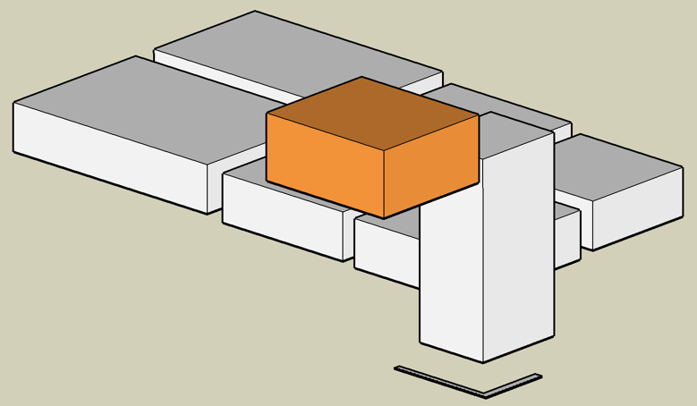
    Occlusion is the most important cue for communicating depth (Not "ambient occlusion", that's a kind of shading, technique #2). Occlusion means that you cannot see an object when it is behind another object.  It's that simple.  But displaying occlusion correctly is the most important part of conveying depth in computer graphics.  In my caffeine video, atoms in the front occlude the atoms behind them.  Fortunately, almost nobody gets this wrong; because everyone recognizes that it looks terrible when it is done wrong.  OpenGL has always used a z-buffer to manage occlusion, so most 3D applications get occlusion right.  Another approach, used by side-scrolling video games, is the "painters algorithm" (draw the stuff in back first) to give a sense of depth by occlusion.

    Occlusion tells me that the orange thing is in front of the other things.

    One interesting display technique that does not respect occlusion, is volume rendering by maximum intensity projection.  Although volume rendering is difficult to do well, the maximum intensity projection method yields a robust rendering of brightness and detail   But the image looks the same whether viewed front-to-back or back-to-front.  I know from experience that this can be confusing.  But the advantages of the maximum intensity projection can sometimes make this tradeoff worthwhile.

  2. Shading

    By shading, I mean all of the realistic colors, gradations, shadows and highlights seen on objects in the real world.  Shading is so important, that when some folks say "3D graphics", all they mean is fancy shading.  This is one area that has been steadily evolving in computer graphics. My caffeine video uses a primitive (by modern standards) Lambertian shading model for the spheres, with a single point light source.  The Lambertian model is sufficient to convey depth and roundness, but looks rather fake compared to state-of-the art rendering.  Part of my excruciating jealousy of QuteMol comes from the clever shading techniques they have used.  For this reason I plan to continue to improve the shading methods in my application.

    Just look at the beautiful shading possible with QuteMol. I'm so jealous:

  3. Perspective 

    Perspective, what artists call foreshortening, is the visual effect that objects close to you appear larger than objects far away from you.  In my caffeine video, nearby atoms appear larger than distant atoms, especially when the molecule is close to the camera.  This is one area where my worship of QuteMol breaks down.  QuteMol appears to use orthographic projection, not perspective.  Close atoms are rendered the same size as distant ones.  But it took me a long time to notice, because QuteMol's beautiful shading is otherwise so effective at communicating depth.
  4. Motion parallax

    There are several ways that motion can reveal depth information by showing parallax, in which closer objects appear more displaced than more distant objects.  When an object rotates or moves, parallax effects reveal important depth information.  In my caffeine video, the rotations of the molecule help to convey the sense of depth.

    Many 3D visualization applications use mouse dragging to rotate the scene.  Users are constantly rotating the scene with the mouse while trying to examine the objects.  These users crave motion parallax.  In response, I have been experimenting with automated subtle wiggling of the scene so the user might not need to constantly drag the mouse.  But I am not sure I have nailed the solution yet.

    Another important source of parallax is when the viewer moves. This is the basis of head tracking in 3D graphics.  Every time I give a stereoscopic 3D demo, the first thing the viewer does after putting on the 3D glasses is to move her head from side to side; because that is the natural response to wanting to maximize the perception of depth.  But it doesn't work; because my applications do not do head tracking (yet).  Motion parallax is more important than stereoscopic 3D.

    The video below from 2007 is a famous example of the effectiveness of head tracking for conveying depth.
  5. Stereoscopy 

    Your left and right eyes see slightly different views of a scene, and your brain can use these two images to perceive your distance from the objects you see.  This is static parallax, as opposed to motion parallax (described in the previous section).  Done properly, stereoscopic viewing can complete the sense of depth in a scene.  But there are a lot of ways to get it wrong.  That is why stereoscopic display must be approached with extreme care.  My caffeine video uses YouTube's awesome stereoscopic support to display the molecule in stereo 3D.  I like viewing it with my Nvidia 3D vision glasses (requires a special 120Hz monitor); though for some reason the aspect ratio is wrong in this mode.   The other 3D modes seem to work fine though.  Part of what I enjoy about stereo 3D is that there are so many details that must be done correctly;  I like details.
  6. Fog 

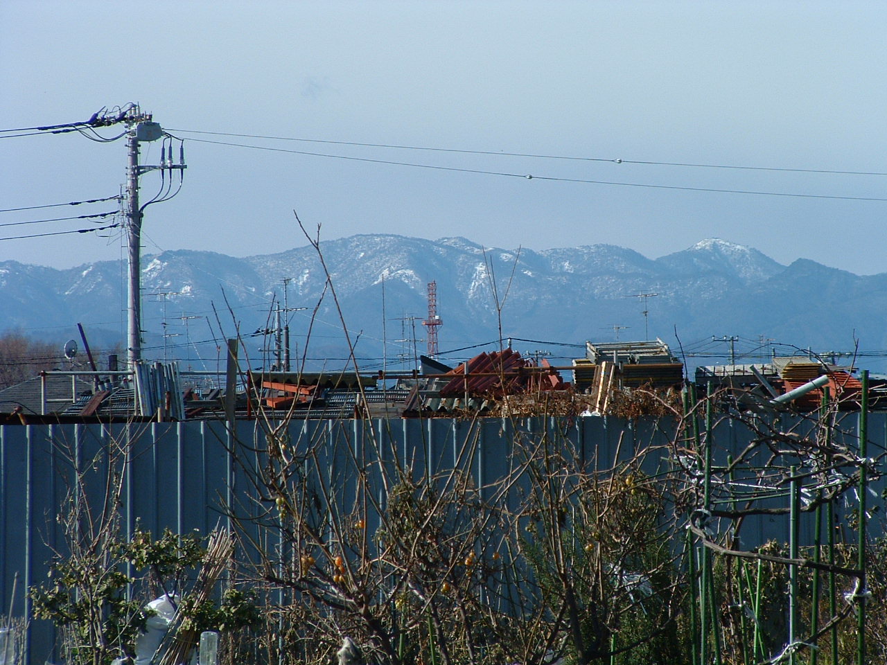
    When you see a mountain on the horizon far away, it appears much paler and bluer than it does close up.  That distant mountain can be almost indistinguishable from the color of sky behind it.  The more distant an object is, the closer its color becomes to the color of the sky.  Even on a clear day, for extremely distant objects, like far off mountains, what I am calling "fog" has an important effect.  On a foggy day, the same thing occurs on a vastly smaller scale.  In either case, that change in color is an important cue about the distance of an object.  In computer graphics, fog (or depth cueing) is easy to compute and has been used for ages, especially when other 3D effects were too hard to achieve. My molecule viewing application uses fog, but at a low setting, and might not be visible in my caffeine video.  Fog is especially important as objects approach the rear clipping plane, to avoid "pop ups", the sudden appearance or disappearance of objects.  It is more pleasing if the objects disappear by gradually receding into the fog.
  7. Depth of field

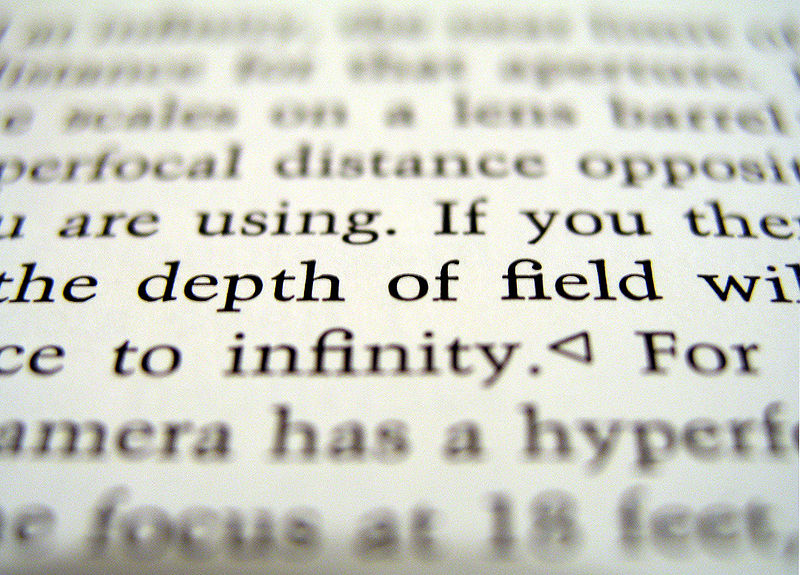
    When you photograph a scene using a wide aperture lens, the focal point of your scene may be in sharp focus, but other objects that are either much closer to the camera or much farther away appear blurry.  This blurriness is a cue that those other objects are not at the same distance as the focal point.  This depth cue can also convey a false sense of scale in trick photography.  An aerial city scene with an extremely narrow depth of field can appear to be just a tiny model of a city.  Depth of field is not widely used in interactive computer graphics, because it is expensive to compute, it's a subtle effect, and to really do it properly, the focused part of the image should follow the user's gaze.  Not just head tracking; but eye tracking would be required.  Even the Hollywood movies make only light use of depth of field; in part because it is not possible to be certain where the audience's gaze is directed.

Most of the techniques I know of can be assigned to one of those seven categories. Have I missed any other depth conveying techniques?   Comments are welcome below.

Sunday, July 08, 2012

Sphere imposters in OpenGL shading language


I recently started a hobby project to create a little OpenGL viewing application. I am experimenting with custom shaders to create sphere imposters. It's working pretty well. Here is a caffeine molecule.

Each sphere uses only two triangles; compared with the thousands of triangles that would be needed to get similar smoothness with the classic OpenGL pipeline.

This week I implemented the custom shaders and various stereoscopic viewing options.  Next I intend to implement interpolated fly-through movie making, and then upload a 3D video to YouTube.

I should also work on measuring and improving performance like I did with my earlier sphere rendering project.  Performance is sluggish when I try to view a protein with thousands of atoms.  But there is a lot of room for improvement.

Four of the five sphere below use the fixed-function OpenGL pipeline, and have hundreds of polygons each.  One sphere has two triangles and uses my shaders.  Can you tell which one?

My inspiration for this sphere imposter project was QuteMol.  I am a long way from achieving what those guys did.  But I am proud of what I have done so far anyway.

Sunday, February 05, 2012

Measuring performance of immediate mode sphere rendering

In my previous post we created a simple hello world OpenGL application. Now we move one step closer to my goal by actually rendering some spheres. And measuring rendering performance.


This program draws a bunch of spheres in immediate rendering mode. This is the slowest possible way of doing it. But it is also the simplest to program and requires the least indirection. If the performance of this approach would meet my needs, I would be happy to use it. But it does not meet my needs. I ideally want the following:
  1. Render over 10000 spheres at once
  2. In under 30 milliseconds
  3. With the most realistic rendering available

It is clear that immediate mode rendering, which is horribly old fashioned, will not come close to meeting these criteria. Let's see how far off we are from the goal.

In this experiment we vary the number of spheres shown, and the number of polygons used to define each sphere. The number of polygons is determined by the second and third arguments to glutSolidSphere(). I set both arguments to the same resolution value, either 10 (spheres look OK, but there are obvious artifacts when zoomed in) or 50 (almost as good as a tesselated sphere can look). And I also varied the number of spheres shown.

Here are the results (click to embiggen):


At each resolution the rendering time is proportional to the number of spheres drawn, as you might expect. At the lower resolution of 10 layers-per-dimension, the rendering time is about 70 microseconds per sphere. At the higher resolution of 50, the rendering time is about 315 microseconds per sphere. To meet my desired performance criteria, the performance would need to be about 0.3 microseconds (300 nanoseconds) per sphere. So we need about a 100-fold speed up from the higher quality rendering to satisfy my needs here.

But there are many approaches ahead. More next time.

The data:

method # spheres resolution frame rate
immediate 1 10 0.3 ms
immediate 1 50 0.4 ms
immediate 3 10 0.4 ms
immediate 3 50 1.1 ms
immediate 10 10 0.9 ms
immediate 10 50 3.4 ms
immediate 30 10 2.1 ms
immediate 30 50 8.9 ms
immediate 100 10 6.8 ms
immediate 100 50 29.0 ms
immediate 300 10 20.1 ms
immediate 300 50 92.3 ms
immediate 1000 10 69.8 ms
immediate 1000 50 315.1 ms

Here is the full source code for the program to run this test:


#!/usr/bin/python

# File sphere_test.py
# Investigate performance of various OpenGL sphere rendering techniques
# Requires python modules PySide and PyOpenGL

from PySide.QtGui import QMainWindow, QApplication
from PySide.QtOpenGL import QGLWidget
from PySide.QtCore import *
from PySide import QtCore
from OpenGL.GL import *
from OpenGL.GLUT import *
from OpenGL.GLU import *
from random import random
from math import sin, cos
import sys


class SphereTestApp(QApplication):
"Simple application for testing OpenGL rendering"
def __init__(self):
QApplication.__init__(self, sys.argv)
self.setApplicationName("SphereTest")
self.main_window = QMainWindow()
self.gl_widget = SphereTestGLWidget()
self.main_window.setCentralWidget(self.gl_widget)
self.main_window.resize(1024, 768)
self.main_window.show()
sys.exit(self.exec_()) # Start Qt main loop


# This "override" technique is a strictly optional code-sanity-checking
# mechanism that I like to use.
def override(interface_class):
"""
Method to implement Java-like derived class method override annotation.
Courtesy of mkorpela's answer at
http://stackoverflow.com/questions/1167617/in-python-how-do-i-indicate-im-overriding-a-method
"""
def override(method):
assert(method.__name__ in dir(interface_class))
return method
return override


class SphereTestGLWidget(QGLWidget):
"Rectangular canvas for rendering spheres"
def __init__(self, parent = None):
QGLWidget.__init__(self, parent)
self.y_rot = 0.0
# units are nanometers
self.view_distance = 15.0
self.stopwatch = QTime()
self.frame_times = []
self.param_generator = enumerate_sphere_resolution_and_number()
(r, n) = self.param_generator.next()
self.set_number_of_spheres(n)
self.sphere_resolution = r

def set_number_of_spheres(self, n):
self.number_of_spheres = n
self.sphere_positions = SpherePositions(self.number_of_spheres)

def update_projection_matrix(self):
"update projection matrix, especially when aspect ratio changes"
glPushAttrib(GL_TRANSFORM_BIT) # remember current GL_MATRIX_MODE
glMatrixMode(GL_PROJECTION)
glLoadIdentity()
gluPerspective(40.0, # aperture angle in degrees
self.width()/float(self.height()), # aspect
self.view_distance/5.0, # near
self.view_distance * 3.0) # far
glPopAttrib() # restore GL_MATRIX_MODE

@override(QGLWidget)
def initializeGL(self):
"runs once, after OpenGL context is created"
glEnable(GL_DEPTH_TEST)
glClearColor(1,1,1,0) # white background
glShadeModel(GL_SMOOTH)
glEnable(GL_COLOR_MATERIAL)
glMaterialfv(GL_FRONT, GL_SPECULAR, [1.0, 1.0, 1.0, 1.0])
glMaterialfv(GL_FRONT, GL_SHININESS, [50.0])
glLightfv(GL_LIGHT0, GL_POSITION, [1.0, 1.0, 1.0, 0.0])
glLightfv(GL_LIGHT0, GL_DIFFUSE, [1.0, 1.0, 1.0, 1.0])
glLightfv(GL_LIGHT0, GL_SPECULAR, [1.0, 1.0, 1.0, 1.0])
glLightModelfv(GL_LIGHT_MODEL_AMBIENT, [1.0, 1.0, 1.0, 0.0])
glEnable(GL_LIGHTING)
glEnable(GL_LIGHT0)
self.update_projection_matrix()
gluLookAt(0, 0, -self.view_distance, # camera
0, 0, 0, # focus
0, 1, 0) # up vector
# Start animation
timer = QTimer(self)
timer.setInterval(10)
timer.setSingleShot(False)
timer.timeout.connect(self.rotate_view_a_bit)
timer.start()
self.stopwatch.restart()
print "RENDER_MODE\tSPHERES\tRES\tFRAME_RATE"

@override(QGLWidget)
def resizeGL(self, w, h):
"runs every time the window changes size"
glViewport(0, 0, w, h)
self.update_projection_matrix()

@override(QGLWidget)
def paintGL(self):
"runs every time an image update is needed"
self.stopwatch.restart()
glClear(GL_COLOR_BUFFER_BIT | GL_DEPTH_BUFFER_BIT)
glColor3f(255.0/300, 160.0/300, 46.0/300) # set object color
self.paint_immediate_spheres(self.sphere_resolution)
self.frame_times.append(self.stopwatch.elapsed())
# Report on frame rate after enough frames have been rendered
if 200 <= len(self.frame_times):
n = len(self.frame_times)
total = 0.0
for t in self.frame_times:
total += t
mean = total / n
print "immediate\t%d\t%d\t%.1f ms" % (self.number_of_spheres, self.sphere_resolution, mean)
# print "mean frame time = %f milliseconds" % (mean)
# Reset state
self.frame_times = [] # Reset list of frame times
try:
(r, n) = self.param_generator.next()
self.set_number_of_spheres(n)
self.sphere_resolution = r
except StopIteration:
exit(0)
# self.set_number_of_spheres(self.number_of_spheres * 2)
self.stopwatch.restart()

def paint_immediate_spheres(self, resolution):
glMatrixMode(GL_MODELVIEW)
for pos in self.sphere_positions:
glPushMatrix()
glTranslatef(pos.x, pos.y, pos.z)
glColor3f(pos.color[0], pos.color[1], pos.color[2])
glutSolidSphere(pos.radius, resolution, resolution)
glPopMatrix()

def paint_teapot(self):
glPushAttrib(GL_POLYGON_BIT) # remember current GL_FRONT_FACE indictor
glFrontFace(GL_CW) # teapot polygon vertex order is opposite to modern convention
glutSolidTeapot(2.0) # thank you GLUT tool kit
glPopAttrib() # restore GL_FRONT_FACE

@QtCore.Slot(float)
def rotate_view_a_bit(self):
self.y_rot += 0.005
x = self.view_distance * sin(self.y_rot)
z = -self.view_distance * cos(self.y_rot)
glMatrixMode(GL_MODELVIEW)
glLoadIdentity()
gluLookAt(x, 0, z, # camera
0, 0, 0, # focus
0, 1, 0) # up vector
self.update()


class SpherePosition():
"Simple python container for sphere information"
pass


class SpherePositions(list):
"Collection of SpherePosition objects"
def __init__(self, sphere_num):
for s in range(sphere_num):
pos = SpherePosition()
# units are nanometers
pos.x = random() * 10.0 - 5.0
pos.y = random() * 10.0 - 5.0
pos.z = random() * 10.0 - 5.0
pos.color = [0.2, 0.3, 1.0]
pos.radius = 0.16
self.append(pos)
assert(len(self) == sphere_num)


def enumerate_sphere_resolution_and_number():
for n in [1, 3, 10, 30, 100, 300, 1000]:
for r in [10, 50]:
yield [r, n]


# Automatically execute if run as program, but not if loaded as a module
if __name__ == "__main__":
SphereTestApp()

Proof of concept OpenGL program in python and Qt/PySide

Here is the output of my initial test program:


I am planning to test the performance of various ways of rendering lots of spheres using OpenGL. I will use python and Qt to run the tests. As a first step, I have created a very light hello program that renders the classic Utah teapot.


#!/usr/bin/python

# File teapot_test.py
# "hello world" type rendering of the classic Utah teapot
# Requires python modules PySide and PyOpenGL

from PySide.QtGui import QMainWindow, QApplication
from PySide.QtOpenGL import QGLWidget
from OpenGL.GL import *
from OpenGL.GLUT import *
from OpenGL.GLU import *
import sys


def override(interface_class):
"""
Method to implement Java-like derived class method override annotation.
Courtesy of mkorpela's answer at
http://stackoverflow.com/questions/1167617/in-python-how-do-i-indicate-im-overriding-a-method
"""
def override(method):
assert(method.__name__ in dir(interface_class))
return method
return override


class SphereTestGLWidget(QGLWidget):
"GUI rectangle that displays a teapot"
@override(QGLWidget)
def initializeGL(self):
"runs once, after OpenGL context is created"
glEnable(GL_DEPTH_TEST)
glClearColor(1,1,1,0) # white background
glShadeModel(GL_SMOOTH)
glEnable(GL_COLOR_MATERIAL)
glMaterialfv(GL_FRONT, GL_SPECULAR, [1.0, 1.0, 1.0, 1.0])
glMaterialfv(GL_FRONT, GL_SHININESS, [50.0])
glLightfv(GL_LIGHT0, GL_POSITION, [1.0, 1.0, 1.0, 0.0])
glLightfv(GL_LIGHT0, GL_DIFFUSE, [1.0, 1.0, 1.0, 1.0])
glLightfv(GL_LIGHT0, GL_SPECULAR, [1.0, 1.0, 1.0, 1.0])
glLightModelfv(GL_LIGHT_MODEL_AMBIENT, [1.0, 1.0, 1.0, 0.0])
glEnable(GL_LIGHTING)
glEnable(GL_LIGHT0)
self.orientCamera()
gluLookAt(0, 0, -10, # camera
0, 0, 0, # focus
0, 1, 0) # up vector

@override(QGLWidget)
def paintGL(self):
"runs every time an image update is needed"
glClear(GL_COLOR_BUFFER_BIT | GL_DEPTH_BUFFER_BIT)
self.paintTeapot()

@override(QGLWidget)
def resizeGL(self, w, h):
"runs every time the window changes size"
glViewport(0, 0, w, h)
self.orientCamera()

def orientCamera(self):
"update projection matrix, especially when aspect ratio changes"
glPushAttrib(GL_TRANSFORM_BIT) # remember current GL_MATRIX_MODE
glMatrixMode(GL_PROJECTION)
glLoadIdentity()
gluPerspective (60.0, self.width()/float(self.height()), 1.0, 10.0)
glPopAttrib() # restore GL_MATRIX_MODE

def paintTeapot(self):
glPushAttrib(GL_POLYGON_BIT) # remember current GL_FRONT_FACE indictor
glFrontFace(GL_CW) # teapot polygon vertex order is opposite to modern convention
glColor3f(0.2,0.2,0.5) # paint it blue
glutSolidTeapot(3.0) # thank you GLUT tool kit
glPopAttrib() # restore GL_FRONT_FACE


class SphereTestApp(QApplication):
"Simple application for testing OpenGL rendering"
def __init__(self):
QApplication.__init__(self, sys.argv)
self.setApplicationName("SphereTest")
self.mainWindow = QMainWindow()
self.gl_widget = SphereTestGLWidget()
self.mainWindow.setCentralWidget(self.gl_widget)
self.mainWindow.resize(1024, 768)
self.mainWindow.show()
sys.exit(self.exec_()) # Start Qt main loop


if __name__ == "__main__":
SphereTestApp()

Monday, March 21, 2011

Autumn 2010 - When Google jumped the shark

I cannot express the depths of my dismay at the "Search instead for..." misfeature that Google has added to search. From the dates of the earliest cries of communal pain on the web, this feature appeared around September 2010.

I am not the only angry customer. Google forums include multiple vigorous discussions of this topic.

TimInBC writes:
I agree, this is annoying, and not because I am promoting a site. I want to FIND stuff, and when I tell it to search for "Orangerie" I don't want it auto-corrected to "Orangutan" or anything else. I am a very good speller and I don't need Google to help me. Please give us a preference to say "Search for exactly what I tell you to search for".

Alensha comments:
It would be really good if this feature was optional instead of being forced on us. I encounter it every day, and it messes up my search results several times daily. Last time I was looking for the meaning of the name of the Egyptian god Atum and of the first 50 results 46 were about the name Autumn, explaining that it means, well, autumn. The "did you mean" function was mostly harmless, but _changing_ the word I typed to something else or filling the first ten pages of the search results with completely irrelevant results is annoying.

This problem seriously interrupts my work flow too. During my work day I run numerous web searches for information. Now that Google is broken, I often find myself concluding "Darn, there must not be any relevant information on this topic on the web." Then I notice that accursed, mocking, evil, cruel cancer of the web, "Search instead for ". The number of near misses convinces me that I must have actually been completely misled many times by Google's cruel practical joke.

Bing is the same way. Here's the deal: Bing, if you create a configuration option to never second guess my search terms, I promise to drop Google and use Bing for my searches. I recommend others make the same promise to Bing.

Sunday, November 22, 2009

YouTube supports 3D stereoscopic video

Google's video service YouTube now supports stereoscopic video. This is great news. I predict that soon it will be possible to stream stereoscopic YouTube videos to stereoscopic monitors.

The only technical information so far is one very long help thread. The Google engineer behind 3d YouTube, "YouTube Pete", participates in that thread.

I would like to take a moment to thank YouTube Pete for his beautiful work on the 3D YouTube project. Kudos to Pete. It is much appreciated.

My hummingbird video


I made a hummingbird video to test out the 3d features myself. The embedded video below does not show the 3D interface. You must go to the YouTube page itself to see the full range of possibilities. Grab a pair of red/blue 3D glasses if you have one.


Remember to check out the original movie to see all of the 3D viewing options.

This hummingbird movie could be improved in several ways
  1. The left side is out of focus. I meant to set the focus for both cameras to 15 cm, but it looks like the focal length of the left eye was set too short.
  2. The sound doesn't seem to work. I plugged in a microphone, and selected the one audio option that was available in AmCap, but I don't hear any sound in the video. This needs to be investigated.
  3. I should register Stereoscopic Multiplexer, to avoid those watermarks on the video. It will cost about $90. Ouch.
  4. It would be good to get more light on the bird. Unfortunately, the sun won't shine on my patio until summer.
  5. The format is Left-Right (parallel), but the emerging YouTube standard is Right-Left (cross-eye), so I should use the Right-Left convention in the future. Plus I have an easier time free-viewing cross-eye, so it will be more convenient for me when viewing embedded videos like the one above. I used the YouTube tag "yt3d:swap=true" to correct for this inversion.

Other YouTube 3D videos


The following are examples of other stereoscopic videos on YouTube, created by others:

This so-called biodiversity documentary contains professional-quality footage of domesticated ducks, geese, and honeybees in India. The narration is done with a top-quality computer generated voice. The voice is only slightly creepy.


This next one is taken with a helmet camera. It is interesting and entertaining. It includes some cityscape images. Unfortunately, a cityscape shows little depth when using a normal human interpupillary distance of 60 mm or so. Hyperstereo might have been nice here.


There are many many other stereoscopic videos on YouTube. Search for "yt3d" on YouTube.

How I made the hummingbird video


I created my hummingbird video using two USB pen cameras. So I could get the two cameras as close as possible. This setup is suited for small, close subjects, such as hummingbirds. Because the two cameras are only 14 mm apart, as opposed to the 60 mm separation of human eyes, my setup yields a view as seen by another hummingbird, rather than what would be seen by a person. This is called hypostereo.

Two USB pen cameras and a portable netbook style computer are the basis of my stereoscopic video system. I created a custom bracket for the cameras so I can mount them on a tripod. The bracket is carefully shaped to compensate for the idiosyncrasies of these particular cameras. These very cheap cameras do not point in exactly the same direction.


The narrow 14 mm distance between the camera lenses is crucial to producing a subtle 3D effect with small close subjects such as the hummingbird. I chose these pen cameras because this form factor permits the smallest camera separation I could find.


Here is a shot of the whole setup prepared to take hummingbird videos.

Saturday, August 22, 2009

Tk 8.5 is better than wxWidgets on Windows

UPDATE: It appears this issue might be fixed in a future release of wxwidgets.

I frequently write computer programs with graphical user interfaces ("GUI"s). I insist that the interfaces look good on Windows, Mac, and Linux computers. By "good", I mean that the widgets (the buttons, sliders, and what-not), look exactly like those found on most other applications developed specifically for that particular platform. For example, buttons and progress bars on Mac must have that clear blue "Aqua" look.

There are several programming tool kits which help to create native-looking user interfaces on multiple platforms. The three platforms I pay particular attention to are Windows, Mac, and Linux. Cross-platform GUI tool kits include wxWidgets, Tk, and Java Swing. This post documents the failure of wxWidgets and Java Swing to respect Windows font sizes.

Look at the following picture to see the failure of wx and Java to respect the Windows font sizes. From left to right, the test programs are in Visual Basic, python/Tk, python/wx, and Java Swing.


wxWidgets looks nice in some cases, but it has some ways to go to support native look and feel on Windows. I am working on several Windows XP systems, on which I routinely select "Large Fonts" in my desktop preferences. wxWidgets does not respect those preferences.

To see the difference, first set extra large fonts on your desktop:

Far click desktop -> Properties -> Appearance -> Font Size -> Extra Large Fonts

Next, write an application using wxWidgets and test whether it respects your font choice. I didn't think so.

If it's any consolation, Java doesn't respect the Windows font size either.

If you want to use a cross-platform widget tool kit, and your definition of "cross-platform" includes Windows, my recommendation is to use Tk 8.5.

The table below summarizes the results for the four test programs I wrote:


GUI tool kits on Windows
Tool KitNative look-and-feel?Respects font size?
Visual basicNo(!)Yes
Tk 8.5YesYes
wx 2.8.10YesNo
Java 1.6.0YesNo


Below are the test programs I wrote to create the windows shown at the beginning of this post.


  • Visual Basic

    ' "Hello, World!" program in Visual Basic.
    Module Hello
    Sub Main()
    MsgBox("Hello, World! (VB)") ' Display message on computer screen.
    End Sub
    End Module


  • Tk 8.5 (tkinter in python 3.1)

    # Note - requires python 3.1 for ttk 8.5 support
    import tkinter as tk
    import tkinter.ttk as ttk

    root = tk.Tk()
    padding = 10
    panel = ttk.Frame(root, padding=padding).pack()
    label = ttk.Label(panel, text="Hello, World! (Tk)")
    label.pack(padx=padding, pady=padding)
    button = ttk.Button(panel, text="Hello", default="active")
    button.pack(padx=padding, pady=padding)
    root.mainloop()


  • wx 2.8.10 (in python 2.6 with wxpython)

    import wx

    padding = 10
    app = wx.App(0)
    frame = wx.Frame(None, -1, "Hello")
    panel = wx.Panel(frame)
    sizer = wx.BoxSizer(wx.VERTICAL)
    panel.SetSizer(sizer)
    text = wx.StaticText(panel, -1, "Hello, World! (wx)")
    sizer.Add(text, 0, wx.ALL, padding)
    button = wx.Button(panel, -1, "Hello")
    sizer.Add(button, 0, wx.ALL, padding)
    frame.Centre()
    frame.Show(True)
    app.MainLoop()


  • Java swing 1.6.0

    import javax.swing.*;
    import java.awt.Dimension;

    public class HelloWorldFrame extends JFrame
    {
    public static void main(String args[])
    {
    new HelloWorldFrame();
    }
    HelloWorldFrame()
    {
    try {
    UIManager.setLookAndFeel(UIManager.getSystemLookAndFeelClassName());
    } catch(Exception e) {}
    JPanel panel = new JPanel();
    add(panel);
    panel.setLayout(new BoxLayout(panel, BoxLayout.PAGE_AXIS));
    panel.setBorder(BorderFactory.createEmptyBorder(10,10,10,10));
    JLabel label = new JLabel("Hello, World! (java)");
    panel.add(label);
    panel.add(Box.createRigidArea(new Dimension(0, 10)));
    JButton button = new JButton("Hello");
    panel.add(button);
    pack();
    setVisible(true);
    }
    }


The wx bug tracker has had a couple of bug reports for this problem, one open for five years. Somehow I doubt they are itching to fix this problem.

The Tk source code that sets the windows correctly appears to be near line 418 of file win/tkWinFont.c in the Tk source code:


if (SystemParametersInfo(SPI_GETNONCLIENTMETRICS,
sizeof(ncMetrics), &ncMetrics, 0)) {
CreateNamedSystemLogFont(interp, tkwin, "TkDefaultFont",
&ncMetrics.lfMessageFont);
CreateNamedSystemLogFont(interp, tkwin, "TkHeadingFont",
&ncMetrics.lfMessageFont);
CreateNamedSystemLogFont(interp, tkwin, "TkTextFont",
&ncMetrics.lfMessageFont);
CreateNamedSystemLogFont(interp, tkwin, "TkMenuFont",
&ncMetrics.lfMenuFont);
CreateNamedSystemLogFont(interp, tkwin, "TkTooltipFont",
&ncMetrics.lfStatusFont);
CreateNamedSystemLogFont(interp, tkwin, "TkCaptionFont",
&ncMetrics.lfCaptionFont);
CreateNamedSystemLogFont(interp, tkwin, "TkSmallCaptionFont",
&ncMetrics.lfSmCaptionFont);
}


The wx source code has similar code in a few locations. But it appears that this technique may be only used for menu fonts and message dialog fonts.

The main problem might be that the method wxGetCCDefaultFont() in the wx source code uses SPI_GETINCONTITLELOGFONT instead of SPI_GETNONCLIENTMETRICS.

Microsoft has documentation for the NONCLIENTMETRICS data structure.

Even if the wx authors fix this today, I fear it will be a long time before the change trickles down into a wxPython release.

Saturday, August 15, 2009

Write your own stereoscopic 3D program using nVidia's "consumer" stereo driver


I have always been a fan of nVidia graphics boards because of their support for 3D stereoscopic games. But the "consumer level" (non-Quadro) stereoscopic drivers only seem to work with games. I have always wondered how to create my own applications that can use the stereoscopic drivers on less-expensive gaming video boards. Now I have found a way.

The "consumer" stereoscopic driver from nVidia only works with "full screen" games. When I started experimenting with OpenGL, I assumed that using the call "glutFullScreen()" might be enough to get the stereoscopic drivers to kick in. But it is not.

The trick is to use the glutEnterGameMode() call. I did a lot of searching on the internet, and nowhere is it mentioned that you must call glutEnterGameMode() to get the nVidia "consumer level" stereoscopic drivers to work. That is why I am sharing this blog post.

My working system is on Windows XP. I am uncertain if this approach will work with Windows Vista/7. I am a bit concerned because nVidia seems to be selling a hardware stereoscopic product these days. I am worried that my custom stereoscopic theater, which uses a pair of polarized video projectors, won't work if I upgrade my Windows version.

Here is how you can do it too, on Windows XP:
  1. Ensure you have a supported nVidia graphics board in your computer. See the stereoscopic driver users' guide for more details.
  2. Get the stereoscopic driver from nVidia. The most recent version (91.31) released for Windows XP is from 2006. That is the one I am using. Consult this driver guide for more details.
  3. Install Python 2.6 and PyOpenGL version 3.0.0, so you can conveniently create OpenGL programs in python.
  4. Familiarize yourself with OpenGL programming. I got started by following the examples of the "red book", the OpenGL Programming Guide.
  5. Study my example program, below, to learn how to call glutGameModeString() and glutEnterGameMode().
Below is the text of a complete working python program that works with the nVidia "consumer level" stereoscopic driver on my Windows XP computer. (The stereoscopic presentation only appears in the full screen gaming mode):

Modify the display() method and the animate() method to show whatever you want!

#!/cygdrive/c/Python26/python

from OpenGL.GL import *
from OpenGL.GLU import *
from OpenGL.GLUT import *
import sys


def do_nothing(*args):
"""
Empty method for glutDisplayFunc during risky transition to game mode.
"""
pass


class HelloOpenGL(object):
"""
Creates a rotating wire frame cube using OpenGL.

Pressing the "f" key toggles full screen game mode.
This full screen mode works with nVidia stereoscopic
driver for Windows XP.
"""
def __init__(self):
self.animation_interval = 100 # milliseconds
self.rotation_angle = 0.0 # degrees, starting point
glutInit("Cube.py")
glutInitDisplayMode(GLUT_RGBA | GLUT_DOUBLE | GLUT_DEPTH)
glEnable(GL_DEPTH_TEST)
glutInitWindowSize(200, 200)
# Remember window id for when we return from game mode.
self.window_id = glutCreateWindow('Wire Cube')
self.initialize_gl_context()
# glutTimerFunc remains when GL context is replaced,
# so it does not go into self.initialize_gl_context()
glutTimerFunc(self.animation_interval, self.animate, 1)
glutMainLoop() # never returns

def clear_gl_callbacks(self):
"""
Set inoccuous callbacks during times when no valid context may be available.
"""
glutDisplayFunc(do_nothing)
glutMotionFunc(None)
glutKeyboardFunc(None)

def initialize_gl_context(self):
"""
When switching between full-screen and windowed modes,
initialize_gl_context() reinitializes state.
"""
glClearColor(0.5,0.5,0.5,0.0)
glutDisplayFunc(self.display)
# glutPassiveMotionFunc(self.mouse_motion)
glutMotionFunc(self.mouse_motion)
glutKeyboardFunc(self.keypress)
# establish the projection matrix (perspective)
glMatrixMode(GL_PROJECTION)
glLoadIdentity()
x,y,width,height = glGetDoublev(GL_VIEWPORT)
gluPerspective(
45, # field of view in degrees
width/float(height or 1), # aspect ratio
.25, # near clipping plane
200, # far clipping plane
)

def start_game_mode(self):
if glutGameModeGet(GLUT_GAME_MODE_ACTIVE):
return # already in game mode
glutGameModeString("800x600:16@60")
if glutGameModeGet(GLUT_GAME_MODE_POSSIBLE):
self.clear_gl_callbacks()
glutEnterGameMode()
self.initialize_gl_context()

def start_windowed_mode(self):
if glutGameModeGet(GLUT_GAME_MODE_ACTIVE):
self.clear_gl_callbacks()
glutLeaveGameMode()
# Remember the window we created at start up?
glutSetWindow(self.window_id)
self.initialize_gl_context()

def display(self):
"""
"display()" method is called every time OpenGL updates the display.
"""
# Erase the old image
glClear(GL_COLOR_BUFFER_BIT | GL_DEPTH_BUFFER_BIT)
# Modelview must be set before geometry is sent
# or else crash when entering stereoscopic mode.
glMatrixMode(GL_MODELVIEW)
glLoadIdentity()
gluLookAt(
0,-0.5,5, # eyepoint
0,0,0, # center-of-view
0,1,0, # up-vector
)
# Rotate about the origin as animation progresses
glRotate(self.rotation_angle, 0, 1, 0)
glPushMatrix()
try:
# Draw the cube
glutWireCube(2.0)
finally:
glPopMatrix()
glutSwapBuffers()

def mouse_motion(self, x, y):
pass

def keypress(self, key, x, y):
if key == '\033':
# Escape key leaves full screen mode
if glutGameModeGet(GLUT_GAME_MODE_ACTIVE):
self.start_windowed_mode()
elif key == "f":
# "f" key toggle full screen and windowed mode.
if glutGameModeGet(GLUT_GAME_MODE_ACTIVE):
self.start_windowed_mode()
else:
self.start_game_mode()

def animate(self, value):
"""
Periodically change the rotation angle for the cube animation.

This animate method() is called as a glutTimerFunc().
"""
self.rotation_angle += 1.0
while self.rotation_angle > 360.0:
self.rotation_angle -= 360.0
glutPostRedisplay()
# Be sure to come back for more
glutTimerFunc(self.animation_interval, self.animate, value+1)


# Run the HelloOpenGL application when this script is run directly.
if (__name__ == '__main__'):
HelloOpenGL()