I have had a cell phone (Treo 680) for about 8 months. I keep it in my front right pants pocket. I always have it set to "vibrate". Lately, my leg has begun to vibrate right where the phone is, causing me to think that the phone is ringing.
It's really creepy.
One time I moved the cell phone away from my leg, but I could still feel the vibration in my leg. I could feel my leg actually vibrating with my hand. I couldn't get it to stop. My leg kept on "ringing" occasionally for quite some time. I have started keeping the phone in a different pocket.
Judging by the number of "I thought it was just me..." responses in a forum I found online, this is a surprisingly common phenomenon. According to this article, it happens when you are expecting a call. I don't get very many calls, so it does not take much!
Yikes!
Who's calling? Is it your leg or your cell phone? — JSCMS
Good vibrations? Bad? None at all? - USATODAY.com
Digg - Have You Noticed the Cell Phone "Phantom Vibration Syndrome"?
Friday, July 13, 2007
Monday, July 09, 2007
Using rxvt in cygwin
I don't like the default cygwin bash window.
To get a nice terminal in cygwin, I have been typing "rxvt" from the cygwin bash shell for years. After several previous abortive attempts, I have finally succeeded in creating a clickable icon that directly launches a nice rxvt (xterm-like) terminal window under Windows.
The solution I found is described at http://freemode.net/archives/000121.html.
I made a few modifications, because I like a larger font, and the batch file did not work for me without modification.
My ~/.Xdefaults file looks like this now:
My replacement for the default "cygwin.bat", which I call "cygwin-rxvt.bat" is as follows:
You will notice that I use tcsh rather than bash. Yes, yes, I know that hard-core UNIX geeks disdain tcsh and only use bash. Shut up. I don't care about you.
Finally, I use a simple prompt with tcsh, which has the side effect of setting the title bar for xterm-like terminals (including rxvt). I add the following line to my .tcshrc file:
To get a nice terminal in cygwin, I have been typing "rxvt" from the cygwin bash shell for years. After several previous abortive attempts, I have finally succeeded in creating a clickable icon that directly launches a nice rxvt (xterm-like) terminal window under Windows.
The solution I found is described at http://freemode.net/archives/000121.html.
I made a few modifications, because I like a larger font, and the batch file did not work for me without modification.
My ~/.Xdefaults file looks like this now:
! ~/.Xdefaults - X default resource settings
Rxvt*geometry: 120x40
Rxvt*background: #000020
Rxvt*foreground: #ffffbf
!Rxvt*borderColor: Blue
!Rxvt*scrollColor: Blue
!Rxvt*troughColor: Gray
Rxvt*scrollBar: True
Rxvt*scrollBar_right: True
! Rxvt*font: Lucida Console-12
Rxvt*font: fixedsys
Rxvt*SaveLines: 10000
Rxvt*loginShell: True
! VIM-like colors
Rxvt*color0:    #000000
Rxvt*color1:    #FFFFFF
Rxvt*color2:    #00A800
Rxvt*color3:    #FFFF00
Rxvt*color4:    #0000A8
Rxvt*color5:    #A800A8
Rxvt*color6:    #00A8A8
Rxvt*color7:    #D8D8D8
Rxvt*color8:    #000000
Rxvt*color9:    #FFFFFF
Rxvt*color10:   #00A800
Rxvt*color11:   #FFFF00
Rxvt*color12:   #0000A8
Rxvt*color13:   #A800A8
Rxvt*color14:   #00A8A8
Rxvt*color15:   #D8D8D8
! eof
My replacement for the default "cygwin.bat", which I call "cygwin-rxvt.bat" is as follows:
@echo off
C:
chdir C:\cygwin\bin
set EDITOR=vi
set VISUAL=vi
set CYGWIN=codepage:oem tty binmode title
set HOME=\cygwin\home\spud
rxvt -e /bin/tcsh -l
You will notice that I use tcsh rather than bash. Yes, yes, I know that hard-core UNIX geeks disdain tcsh and only use bash. Shut up. I don't care about you.
Finally, I use a simple prompt with tcsh, which has the side effect of setting the title bar for xterm-like terminals (including rxvt). I add the following line to my .tcshrc file:
set prompt="%{\033]0;%~%L\007%}\[%h\]> "
Sunday, April 22, 2007
Extracting the magnitude component of an image Fourier transform
 New result!
I finally succeeded in extracting the magnitude component of the image Fourier transform (shown at right).
Recapping the story so far
I previously created a picture of a bird, and a slightly translated version of the same image. I intend to use these images to test ideas about using the Fourier transform to automatically align pairs of images to create aligned stereoscopic pairs.
The input images, show in the previous post, are summarized below:

Original image
Translated version of the original image, for testing my hypothesis.

Fourier transform of original, masked image.
Fourier transform of translated, masked image
I took the plunge and learned to write a filter using the pbmplus environment (see previous post). Here is the program as I wrote and used it for this post:
The new PGM filter I made
I understand that it is tedious to mix GIMP and PBM tools in an image processing pipeline. Perhaps I will port the FFT image processing to PBM later...
What follows next is C language source code I just now wrote for a new image filter in the PBMPlus or NetPBM image processing tool kit:
Original vs. translated images in Fourier magnitude space:
/* pgm_fourier_recast.c - read a portable graymap produced by the
** GIMP Fourier plug-in, and extract magnitude and phase components
**
** Copyright (C) 2007 by biospud@blogger.com
**
** Permission to use, copy, modify, and distribute this software and its
** documentation for any purpose and without fee is hereby granted, provided
** that the above copyright notice appear in all copies and that both that
** copyright notice and this permission notice appear in supporting
** documentation.  This software is provided "as is" without express or
** implied warranty.
*/

/*
** 1) Place source file pgm_fourier_recast.c in directory with working build of netpbm/editor
** 2) Add "pgm_fourier_recast" to list of files in Makefile
** 3) "make pgm_fourier_recast" from netpbm/editor directory
*/

#include <stdio.h>
#include <math.h>
#include "pgm.h"

typedef struct pgm_image_struct {
int height;
int width;
gray maximumValue;
gray** data;
} PgmImage;

PgmImage getInputImage( int argc, char *argv[] );
PgmImage convertFourierToPhaseMagnitude(PgmImage inputImage);
void writeImageAndQuit(PgmImage outputImage);
double gimpFourierPixelToDouble(PgmImage image, int x, int y);
double getNormalizationFactor(PgmImage image, int x, int y);
gray doubleToGimpFourierPixel(double value, PgmImage image, int x, int y);

int main( int argc, char *argv[] )
{
PgmImage inputImage;
PgmImage outputImage;

inputImage = getInputImage(argc, argv);
outputImage = convertFourierToPhaseMagnitude(inputImage);
writeImageAndQuit(outputImage);
}

PgmImage getInputImage( int argc, char *argv[] ) {
const char* const usage = "[pgmfile]";
int argn;
FILE* inputFile;

PgmImage answer;

pgm_init( &argc, argv );

argn = 1;

if ( argn < argc ) {
  inputFile = pm_openr( argv[argn] );
  ++argn;
} else {
  inputFile = stdin;
}

if ( argn != argc )
pm_usage( usage );

answer.data = pgm_readpgm(
    inputFile,
    &answer.width,
    &answer.height,
    &answer.maximumValue
    );

pm_close( inputFile );

return answer;
}

double gimpFourierPixelToDouble(PgmImage image, int x, int y) {
/*
** based on source code at
** http://people.via.ecp.fr/~remi/soft/gimp/gimp_plugin_en.php3
*/

gray pixel = image.data[x][y];

/*
** renormalize
** from (range 0 -> 255)
** to range (-128 -> +127),
*/
double d128 = (double)(pixel) - 128.0; /* double128() */

double bounded = (d128 / 128.0); /* unboost() */
double unboosted0 = 160 * (bounded * bounded); /* unboost() */
double unboosted = d128 > 0 ? unboosted0 : -unboosted0;  /* unboost() */

double answer = unboosted / getNormalizationFactor(image, x, y);

return answer;
}

/* Normalization factor that corrects scale of Fourier transform
** pixel based upon distance from origin
*/
double getNormalizationFactor(PgmImage image, int x, int y) {
/*
** based on source code at
** http://people.via.ecp.fr/~remi/soft/gimp/gimp_plugin_en.php3
*/
double cx = (double)abs(x - (image.width + 1)/2 + 1);
double cy = (double)abs(y - (image.height + 1)/2 + 1);
double energy = (sqrt(cx) + sqrt(cy));
return energy*energy;
}

gray doubleToGimpFourierPixel(double value, PgmImage image, int x, int y) {

double normalized = value * getNormalizationFactor(image, x, y);
double bounded = fabs( normalized / 160.0 );
double boosted0 = 128.0 * sqrt (bounded);
double boosted = (value > 0) ? boosted0 : -boosted0;

/*
** renormalize
** from range (-128 -> +127),
** to (range 0 -> 255)
*/
int answer = (int)boosted + 128;
if (answer >= 255) return 255;
if (answer <= 0) return 0;
return answer;
}

PgmImage convertFourierToPhaseMagnitude(PgmImage inputImage) {
PgmImage answer;
int outRows = inputImage.height;
int outCols = inputImage.width;
int row, col;

double realDouble, imaginaryDouble;
double magnitudeDouble, phaseDouble;
gray realPixel, imaginaryPixel;
gray magnitudePixel, phasePixel;

int doUsePhase = 0;

answer.height = outRows;
answer.width = outCols;
answer.maximumValue = inputImage.maximumValue;
answer.data = pgm_allocarray( outCols, outRows );

for ( row = 0; row < outRows; ++row ) {
  for ( col = 0; col < outCols; col += 2) {
        /* get pixel values from image */
        realPixel = inputImage.data[row][col];
        imaginaryPixel = inputImage.data[row][col + 1];

        /* convert to doubles */
        realDouble = gimpFourierPixelToDouble(inputImage, row, col);
        imaginaryDouble = gimpFourierPixelToDouble(inputImage, row, col);

        /* convert real/imaginary to magnitude/phase */
        magnitudeDouble = sqrt(
            realDouble * realDouble +
            imaginaryDouble * imaginaryDouble
            );

        /* convert to pixel values */
        magnitudePixel = doubleToGimpFourierPixel(
            magnitudeDouble,
            inputImage, row, col
            );

        if (doUsePhase) {
            phaseDouble = atan2(imaginaryDouble, realDouble);

            phasePixel = (int)(256.0 * phaseDouble / (2.0 * 3.14159));
            while (phasePixel > 255) phasePixel -= 256;
            while (phasePixel < 0) phasePixel += 256;
        }

        /*
        i1 = inputImage.data[row][col];
        v = gimpFourierPixelToDouble(inputImage, row, col);
        i2 = doubleToGimpFourierPixel(v, inputImage, row, col);
        printf("%.3g\t%.3g\t%.3g\t%.3g\n",
            realDouble, imaginaryDouble, magnitudeDouble, phaseDouble);
        */

      answer.data[row][col] = magnitudePixel;

        if (doUsePhase)
          answer.data[row][col + 1] = phasePixel;
        else
          answer.data[row][col + 1] = magnitudePixel;

    }
}

return answer;
}

void writeImageAndQuit(PgmImage outputImage) {
/* Write resulting image */
pgm_writepgm(
    stdout,
    outputImage.data,
    outputImage.width,
    outputImage.height,
    outputImage.maximumValue,
    0
    );

/* and clean up */
pm_close( stdout );
pgm_freearray(
    outputImage.data,
    outputImage.height
    );

exit( 0 );
}
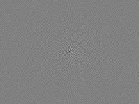
Phew! After writing this filter, I created the following "magnitude only" versions of the test images:

Original: Magnitude component of Fourier transform of original image
Translated: Magnitude component of Fourier transform of translated image
A superficial look suggests that the magnitude component is in fact very similar between the two images. But for automation, I need a quantitative measure to decide how similar two images are. More next time...
Thursday, April 19, 2007
Testing my Fourier transform hypothesis
In the past few posts I have repeatedly assumed that the magnitude component of the Fourier transform of an image will be relatively unchanged when the original image is translated vertically and/or horizontally. My next task should be either prove or disprove this hypothesis before going much further.
Let's start with two gray-scale images that differ only in horizontal alignment for testing. If my intuition is correct, the magnitude portion of the Fourier transform should differ only slightly between the two images.
I downloaded and installed NetPBM, to facilitate command line processing of images. I suspect that it will be easier for me to write new pbm filters than to write GIMP plug-ins.
One infuriating thing about NetPBM is that one of the maintainers has destroyed many of the original man pages in an effort to "simplify" the distribution. I genuinely appreciate this dude taking on the responsibility to maintain the code, but this one horrible documentation decision has caused me to curse out loud many times in the past several years. My feelings are neatly summed up by the observations of another user on the netbsd packaging discussion list:
Hear hear.
In any case, here is a visual overview of the experiment set-up:

Original image
Translated version of the original image, for testing my hypothesis.
If I am right about the Fourier transform, the magnitudes of the Fourier transform will be almost the same between the original image and the translated one. This will simulate the comparison of stereo pairs that do not perfectly line up.

Gray version of the translated image
To simplify the analysis, I created a gray-scale version of the images, so the issue of the color channels does not complicate the analysis.

The mask I used to "remove" the edges of the images
Recall from my earlier posting that the blurry circle mask is used to reduce edge artifacts in the Fourier transform.

Apply circle mask to untranslated image

Masked version of translated image
Fourier transform of original, masked image.
Fourier transform of translated, masked image
Next I need to extract the magnitudes of the Fourier transforms and compute the similarities between the images. I have some ideas of how to do this, but it will require more work. I expect that the PBM tools will come in handy here. More next time...
Let's start with two gray-scale images that differ only in horizontal alignment for testing. If my intuition is correct, the magnitude portion of the Fourier transform should differ only slightly between the two images.
I downloaded and installed NetPBM, to facilitate command line processing of images. I suspect that it will be easier for me to write new pbm filters than to write GIMP plug-ins.
One infuriating thing about NetPBM is that one of the maintainers has destroyed many of the original man pages in an effort to "simplify" the distribution. I genuinely appreciate this dude taking on the responsibility to maintain the code, but this one horrible documentation decision has caused me to curse out loud many times in the past several years. My feelings are neatly summed up by the observations of another user on the netbsd packaging discussion list:
"...I want the manual as released with the code I'm using, no changes after the fact. Release your manuals, don't blog them. it is *IMPOSSIBLE* for me to get that manual, no matter how many hoops I jump through, because you cannot (as they suggest) 'wget' an old version of the manual, one which still has manual pages instead of links to other non-Netpbm projects featured on the top page, one which has actual documentation for pnmscale rather than a three-page rant about why I should switch to Netpam..."
Hear hear.
In any case, here is a visual overview of the experiment set-up:
Original image
One thing I will need is a method to compare how similar two images are. As a control, I will be comparing the original image to itself.
Translated version of the original image, for testing my hypothesis.
If I am right about the Fourier transform, the magnitudes of the Fourier transform will be almost the same between the original image and the translated one. This will simulate the comparison of stereo pairs that do not perfectly line up.
Gray version of the translated image
To simplify the analysis, I created a gray-scale version of the images, so the issue of the color channels does not complicate the analysis.

The mask I used to "remove" the edges of the images
Recall from my earlier posting that the blurry circle mask is used to reduce edge artifacts in the Fourier transform.

Apply circle mask to untranslated image
Masked version of translated image
Finally, create the two Fourier transforms, one for the untranslated image and one for the translated image:
Fourier transform of original, masked image.
Fourier transform of translated, masked image
Next I need to extract the magnitudes of the Fourier transforms and compute the similarities between the images. I have some ideas of how to do this, but it will require more work. I expect that the PBM tools will come in handy here. More next time...
Sunday, April 15, 2007
Investigating the GIMP Fourier transform
In my previous post I began to work up how we might use the Fourier transform to help align two images that form a 3D stereoscopic image pair.
A more detailed investigation reveals that we need to ask a few more questions.
I sort of understand what the Fourier transform means for scalar data. But in an image, there are three different channels of color information, usually decomposed in one of two ways.
Two different representations of three-dimensional color data in an image pixel:
Two different representations of a two dimensional complex number:
 Two ways of representing a complex number: magnitude/phase and real/imaginary
The bottom line here is that is seems to me that the Fourier transform should have twice as much data as the original image, since the Fourier transform takes regular real numbers, and generates complex numbers. So a regular 3-channel image should create a Fourier transform with 6 channels. So what exactly is in the Fourier transform generated by the GIMP plug-in?
Unfortunately the documentation for the plug-in is in French, and I have not studied French since the mid-1970s.
Understanding how the transform data are represented is especially important at this point for two reasons:
I did some experimentation and determined that the red channel of the Fourier transform corresponds to the red channel of the original image, etc. Excellent.
Further, the French documentation is surprisingly intelligible when filtered through AltaVista babelfish. I still don't quite understand all of the details, but it appears that the complex values are stored in pairs of subsequent pixels, representing the logarithm of the real component, followed by the logarithm of the imaginary component. This is bad news. I want the magnitude of the complex number, which is equal to the square root of the sum of the squares of the real and imaginary components (using Pythagoras' theorem). It will be hairy to extract that information. So I need to either a) find another Fourier transform image filter, b) write a GIMP plug-in that further processes these Fourier transform images, c) think of some other trick, or d) abandon this project.
By the way, if you read the English translation of the French documentation, there is a good explanation of why, near the end of the article, he compares his simulated image to a "moose". It turns out that the French word for "moose" is "orignal", while the French word for "original" is "original". The author made a typo, misspelling "original" to accidentally type another actual French word. Thus his spell-checker did not catch it. I believe he meant to say that the simulated image resembles the original image, not that it resembles a moose. Or not. Who knows?
I will cogitate some more on what to do next. More next time...
A more detailed investigation reveals that we need to ask a few more questions.
I sort of understand what the Fourier transform means for scalar data. But in an image, there are three different channels of color information, usually decomposed in one of two ways.
Two different representations of three-dimensional color data in an image pixel:
- red, green, and blue (RGB), or alternatively as
- hue, saturation, and brightness. (HSV)
Two different representations of a two dimensional complex number:
- Real component and Imaginary component
- Magnitude and phase
 Two ways of representing a complex number: magnitude/phase and real/imaginary
The bottom line here is that is seems to me that the Fourier transform should have twice as much data as the original image, since the Fourier transform takes regular real numbers, and generates complex numbers. So a regular 3-channel image should create a Fourier transform with 6 channels. So what exactly is in the Fourier transform generated by the GIMP plug-in?
Unfortunately the documentation for the plug-in is in French, and I have not studied French since the mid-1970s.
Understanding how the transform data are represented is especially important at this point for two reasons:
- The whole trick of using the Fourier transform to ignore the horizontal/vertical translation component requires that we use only the magnitude of the complex numbers (which does not depend upon the image translation), and ignore the phase component (which depends exquisitely upon the image translation).
- Where are the six channels of data that should be coming from the Fourier transform?
I did some experimentation and determined that the red channel of the Fourier transform corresponds to the red channel of the original image, etc. Excellent.
Further, the French documentation is surprisingly intelligible when filtered through AltaVista babelfish. I still don't quite understand all of the details, but it appears that the complex values are stored in pairs of subsequent pixels, representing the logarithm of the real component, followed by the logarithm of the imaginary component. This is bad news. I want the magnitude of the complex number, which is equal to the square root of the sum of the squares of the real and imaginary components (using Pythagoras' theorem). It will be hairy to extract that information. So I need to either a) find another Fourier transform image filter, b) write a GIMP plug-in that further processes these Fourier transform images, c) think of some other trick, or d) abandon this project.
By the way, if you read the English translation of the French documentation, there is a good explanation of why, near the end of the article, he compares his simulated image to a "moose". It turns out that the French word for "moose" is "orignal", while the French word for "original" is "original". The author made a typo, misspelling "original" to accidentally type another actual French word. Thus his spell-checker did not catch it. I believe he meant to say that the simulated image resembles the original image, not that it resembles a moose. Or not. Who knows?
I will cogitate some more on what to do next. More next time...
Use of Fourier transform in aligning stereoscopic image pairs
In my previous post, I wondered how to begin to determine parameters for aligning two images, when no other parameters have yet been determined.
One concept that can help is the Fourier transform. The Fourier transform can be used to eliminate the vertical and horizontal alignment components from the analysis. Thus we should be able to determine certain parameters, such as scale and rotation, without having to first solve the vertical and horizontal alignment problem.
The GIMP image tool has a plug-in that permits computation of the Fourier transform of an image. (Presumably Photoshop has a similar tool).
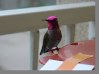
The unmodified left-eye view from yesterday
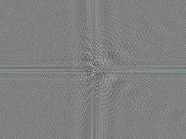 Fourier transform of the same bird image, as generated by the GIMP plug in.
Believe it or not, the Fourier transform contains all of the information necessary to reconstruct the original image.
It is difficult for the human eye to make sense of the Fourier transform image. The two largest features are a big vertical stripe down the middle, and a horizontal stripe across the center. Unfortunately, these features are a BAD thing. They show that the Fourier transform is dominated by something I don't care about.
What features of the original image have strong horizontal and vertical components, causing the primary features of the Fourier transform? This is perhaps a subtle point: the edges of the image cause these features. This is a problem. If we want to use the Fourier transform to detect the relative rotation between two images, we cannot have the edges of the image dominating the Fourier transform. The vertical and horizontal edges of the images will be used to form the rotational alignment, and no rotation will occur.
The solution is to remove the edges of the image before taking the Fourier transform. But how do you remove the edges of an image? Like this:
 Bird image with "edges removed"
I created a circular mask for the imtage, so that it would be radially symmetric, thus minimizing image shape artifacts in lining up the relative rotation of two images. Further, I made the mask a blurry circle, figuring that a blurry edge would have more localized effects on only the low-resolution region of the Fourier transform. The new Fourier transform of the "edge-removed" version of the bird is much smoother:
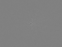
 Fourier transform of edge-removed bird image
It now becomes clear that many of the other primary features of that initial Fourier transform were also "ringing" artifacts related to the edge effect. To sum up the results so far:
One concept that can help is the Fourier transform. The Fourier transform can be used to eliminate the vertical and horizontal alignment components from the analysis. Thus we should be able to determine certain parameters, such as scale and rotation, without having to first solve the vertical and horizontal alignment problem.
The GIMP image tool has a plug-in that permits computation of the Fourier transform of an image. (Presumably Photoshop has a similar tool).
The unmodified left-eye view from yesterday
 Fourier transform of the same bird image, as generated by the GIMP plug in.
Believe it or not, the Fourier transform contains all of the information necessary to reconstruct the original image.
It is difficult for the human eye to make sense of the Fourier transform image. The two largest features are a big vertical stripe down the middle, and a horizontal stripe across the center. Unfortunately, these features are a BAD thing. They show that the Fourier transform is dominated by something I don't care about.
What features of the original image have strong horizontal and vertical components, causing the primary features of the Fourier transform? This is perhaps a subtle point: the edges of the image cause these features. This is a problem. If we want to use the Fourier transform to detect the relative rotation between two images, we cannot have the edges of the image dominating the Fourier transform. The vertical and horizontal edges of the images will be used to form the rotational alignment, and no rotation will occur.
The solution is to remove the edges of the image before taking the Fourier transform. But how do you remove the edges of an image? Like this:
 Bird image with "edges removed"
I created a circular mask for the imtage, so that it would be radially symmetric, thus minimizing image shape artifacts in lining up the relative rotation of two images. Further, I made the mask a blurry circle, figuring that a blurry edge would have more localized effects on only the low-resolution region of the Fourier transform. The new Fourier transform of the "edge-removed" version of the bird is much smoother:
 Fourier transform of edge-removed bird image
It now becomes clear that many of the other primary features of that initial Fourier transform were also "ringing" artifacts related to the edge effect. To sum up the results so far:
- The Fourier transform looks like it might theoretically be a useful tool for determining the scale and/or rotation relationship between two images, without needing to first determine the translational components.
- If we end up using the Fourier transform in this way, we should include a pre-processing step in which we make a blurry-edged circular version of the two images to be compared.
Toward automatic alignment of stereoscopic image pairs
When aligning the two images of a stereoscopic pair, we wish to determine the following parameters:
I will attempt to attack the problem of determining each parameter in turn, in subsequent posts.
- Scale: The relative scale between the two images. Usually close to 1.0, but might vary if two cameras were used with slightly different zoom or distance.
- Rotation: There may be a small relative rotation between the two images, either clockwise or counterclockwise. This can be tedious to determine manually.
- Eye axis: The direction relating the left eye to the right eye is usually left to right, but might be off by a small angle. For various special ad hoc stereoscopic techniques, such as 3D photos of the moon, determining this direction is very important. It is tedious and imprecise to determine this axis manually. Most folks just assume that the eye axis is perfectly horizontal and move on.
- Translation: Alignment in the left/right direction and in the up/down direction.
- Up/down: There is a single clear value for the correct alignment in the up/down direction, perpendicular to the eye axis. This value can be determined manually, but should be amenable to automatic determination as well.
- Left/right: Alignment along the eye-axis varies from pixel to pixel depending upon the depth of the subject. This is how 3D photos work. Determining left/right alignment may be the hardest part to automate.
- Up/down: There is a single clear value for the correct alignment in the up/down direction, perpendicular to the eye axis. This value can be determined manually, but should be amenable to automatic determination as well.
- Brightness and color balance: Especially when the two images are taken with two cameras, as in my set-up, the two images may differ in brightness and color balance. These differences should be corrected before generating a final stereo pair.
The images above are a typical example of a raw stereoscopic pair. The two images obviously differ in color balance, vertical alignment, and horizontal alignment.
I will attempt to attack the problem of determining each parameter in turn, in subsequent posts.
Saturday, April 07, 2007
Hummingbird with tongue hanging out
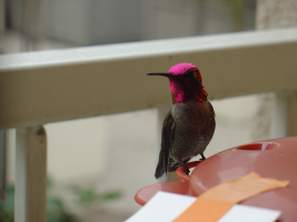
 Juvenile male Anna's hummingbird (Calypte anna) tasting the air
Just now I got a nice photo of a hummingbird sticking his tongue out (click bird for larger image). Notice the fine silvery tongue extending beyond the tip of the beak. This photo represents about the limit of image resolution I will be able to acheive with my current optical set-up. I am pretty happy with this resolution. Unfortunately, in this particular shot the companion camera image was out of focus, so there will be no stereoscopic version of this tongue shot forthcoming. (Not that I have yet created any 3D photos good enough to post!)
Today's shoot was my first success at getting decent photos using mirrors. Previously my mirror photos were too blurry and displayed second reflection artifacts. Today I used first surface mirrors mounted more securely. That seems to have done the trick! Now perhaps I will be able to get stereoscopic photos with a smaller interpupilary separation. With today's mirror setup, the separation is about 50 mm, which is still sort of big at this 400 mm distance. I don't know how I can get it smaller though.
Wednesday, April 04, 2007
What a coincidence! Here's one with a full purple head now!
 Deep magenta throat and crown of male Anna's hummingbird (Calypte anna)
(click bird for larger image)
Yesterday I said that the male Anna's hummingbird can have a completely magenta head. On cue, my charming bride captured this image of a male in full display. I guess the male in the earlier pictures is either a hybrid species, a juvenile, or just a mutant. Perhaps it helps that the sky was overcast today.
Tuesday, April 03, 2007
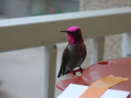
Male Anna's hummingbird at even higher resolution.
 Male Anna's Hummingbird (Calypte anna) in repose at feeder
This species, Anna's hummingbird (Calypte anna), is the only hummingbird species in which the crown (top of the head) of the male can also appear crimson (in addition to the throat). If you look carefully at the photo above, you can see a few reddish feathers on the head. Google image search for "Anna's Hummingbird" and you will find many images of male birds in which the entire head glows with a brilliant magenta color. You have to view the bird from just the right angle to get that effect.
On the lower left of this bird's throat is a region that is yellow-green, almost the exact complementary (opposite) color to the red-magenta seen on the rest of the throat. I suspect that the complementary color viewed from a different angle is no coincidence. It reminds me of the cytological stain eosin, which is colored red-magenta when you view light through the solution, but is yellow-olive when you view light reflected off of the solution's surface. Eosin is one of the important stains used in Pap smears, and many other important microscopic tissue staining methods.
Monday, April 02, 2007
Today's hummingbird pictures


Saturday, March 24, 2007
First clear Danio photo

I just took this picture of a Danio (zebrafish) in our fish tank. I used a flash, so I had to take the picture from an angle so that I didn't just take a picture of the reflection of the flash. As with the hummingbird pictures, I took this with a two camera set up, so that I can create stereoscopic pictures. Once I get better at composing the stereo pairs, I will start posting 3D pictures. It is possible that I will make 3D versions of these same pictures that I am posting now.
Sunday, March 18, 2007
New hummingbird pictures.

We started filling our hummingbird feeder about two weeks ago. I think we already have a nesting pair settling down nearby. I got some nice pictures this morning when the sun was shining on the feeder. Shown here is a female.
Subscribe to:
Posts (Atom)