Last time we textured the plane with a simple procedural texture. Now we add a proper image texture. First we use the texture coordinates from the procedural texture in part 2, to place a repeated version of a proper image on our infinite plane.
Filtering
Without texture filtering, we see many artifacts. Notice the graininess toward the horizon. Also note the Moire patterns in the patterns of parallel lines at near to mid distance: |
| Inifinite plane tiled with an unfiltered image texture. The image looks sorta OK up close, but everything is grainy at larger distances, and patterns of fine lines look bad even at moderate distances. |
We can clear up most of those artifacts with trilinear filtering. When creating the texture, call
glGenerateMipmap(GL_TEXTURE_2D); glTexParameteri(GL_TEXTURE_2D, GL_TEXTURE_MIN_FILTER, GL_LINEAR_MIPMAP_LINEAR); |
| Compared to the earlier unfiltered image, this trilinear filtered view avoids most of the artifacts. But the areas near the horizon get too blurry too fast. |
Regular texture filtering does not work perfectly for oblique viewpoints, which is always the case near the horizon for our infinite plane. We need to use a technique called anisotropic filtering, which applies different filtering in different directions. Anisotropic filtering is not supported in pure OpenGL, so you need to load an extension GL_TEXTURE_MAX_ANISOTROPY_EXT and use it like this.
glGetFloatv(GL_MAX_TEXTURE_MAX_ANISOTROPY_EXT, &f_largest); glTexParameterf(GL_TEXTURE_2D, GL_TEXTURE_MAX_ANISOTROPY_EXT, f_largest);With anisotropic filtering, the texture pattern looks better near the horizon (below):
 |
| Anisotropic filtering looks better by increasing the sharpness near the horizon. There remain some minor artifacts and shimmering, especially when viewed in VR. But this is the best I know how to do. Besides, we would ordinarily use much less demanding texture images. This texture is specifically designed to reveal display imperfections. |
Using a more natural texture image, like the patch of grass below, shows no artifacts when viewed in VR using anisotropic filtering:

After gazing at this infinite vista of grass in VR, the game "Infinimower" practically writes itself.
Efficiency and Antialiasing
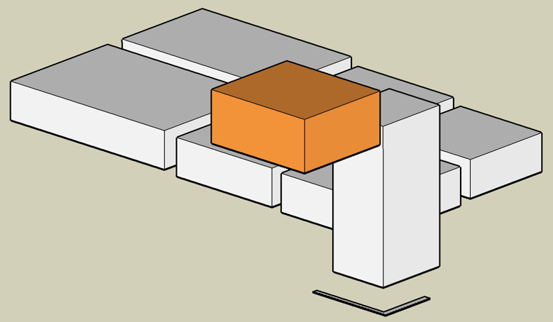
Up to this point we have been inefficiently drawing the plane. The vertex shader creates a procedural triangle strip covering the entire screen, and the fragment shader rejects all the pixels not on the infinite plane using the "discard" command. So even if you are looking up, away from the plane, the fragment shader is still executed for every single pixel on the screen. We can be more efficient than this, and also solve the problem of antialiasing at the horizon line at the same time. |
| So far we have been using a procedural vertex buffer, defined in the vertex shader, that covers the entire visible screen (pink rectangle). This is inefficient because the fragment shader gets invoked for each sky pixel too, even though these are never displayed. |
 |
| Here we use a more carefully selected vertex set, that matches the exact visible area of the infinite plane. This is a more efficient imposter geometry. |
It would be possible to compute the optimal vertices on the host side, but today we'll compute it using a geometry shader program.
This also solves the horizon aliasing problem. Now that we have a triangle boundary along the horizon, it can be antialiased using multisample antialiasing (MSAA). This is a widely used technique so I won't describe the details here.
Shader source code is at https://gist.github.com/cmbruns/5b1c2b211766cdcb3b29689e0c32a63d
Next Time:
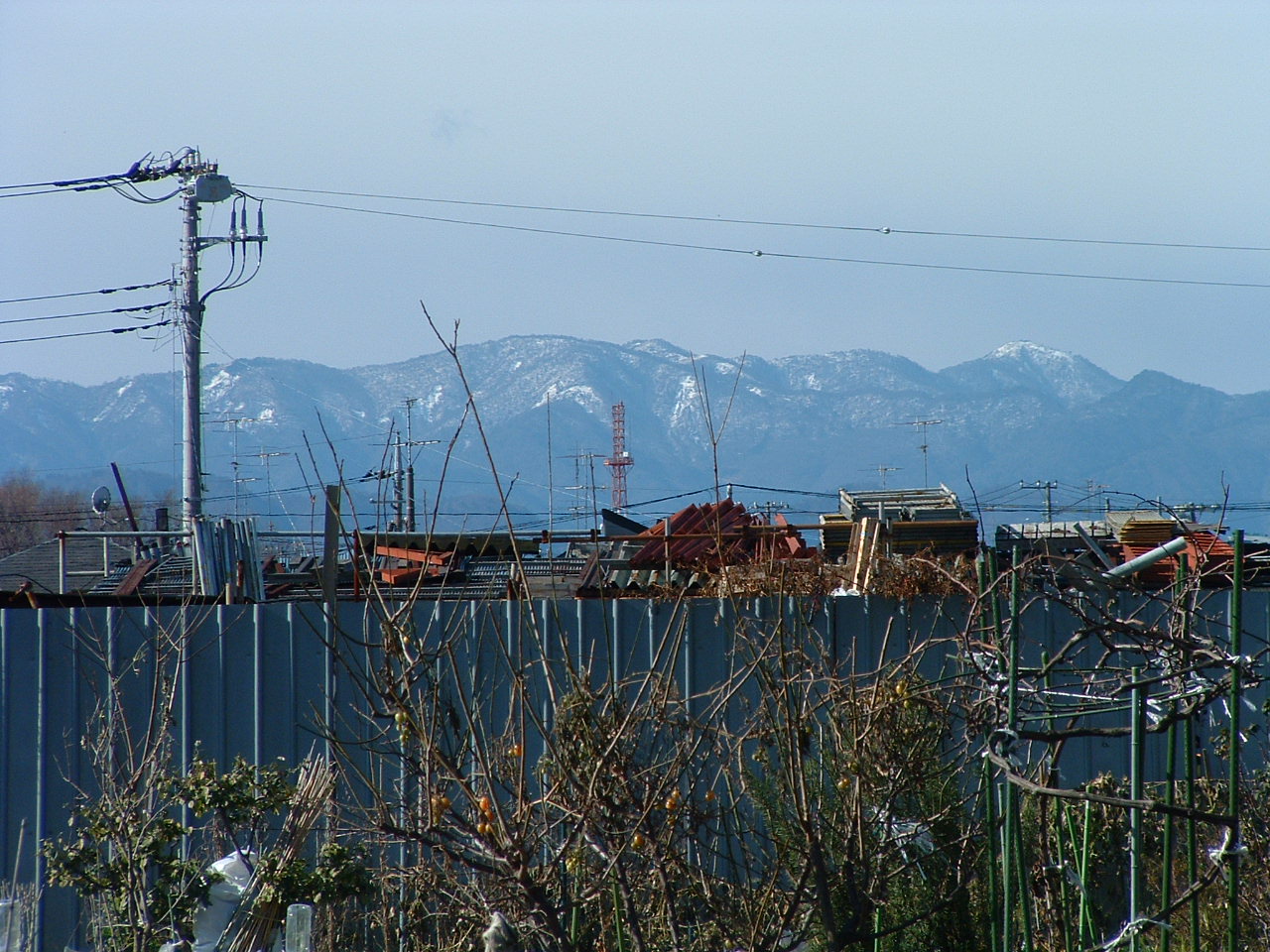
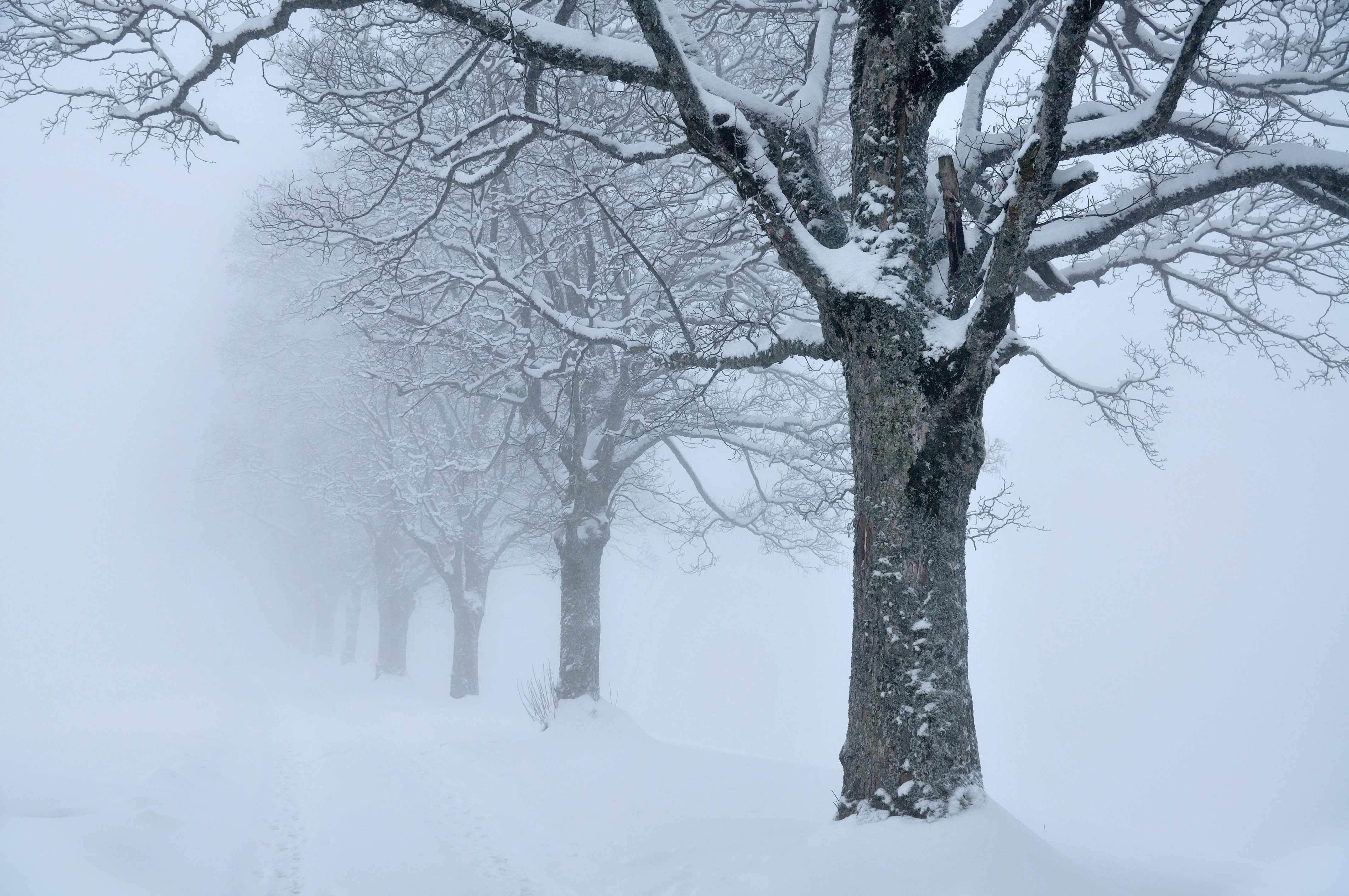
- Using a 360 photo to cover the entire plane.


